background image

User Manual 

2018 Cervis, Inc. 

7.0 

SmaRT EBU-xH24XF Specifications 

Table 8. EBU-xH24XF Base Unit Specifications 

Item 

Description 

Power 

Vin 

+7 to +28VDC 

Radio 

Frequency 

License 

Modulation 

Antenna 

906-924MHz @ 10mW; 2405-2480MHz @ 100mW 

Free 

DSSS  

External or Internal 

Environment 

Operating Temp 

Storage Temp 

Humidity 

-20°C to 55°C (-4°F to 131°F) 

-40°C to 85°C (-40°F to 185°F) 

0 to 100% 

Indicators (5) 

– Power 

– OUT/IN 


– HEALTH 

– RF TX/RX 

– CAN TX/RX 

OK when amber 

Green 

– output(s) only active; Red-input(s) only active 

Amber 

– output(s) and input(s) active 

Blinking when active 

Red 

– TX only active; Green-RX only active; Amber TX/RX active 

Red 

– TX only active; Green-RX only active; Amber TX/RX active 

Enclosure 

Dimensions 

Durability 

Mounting Holes 


Weight 

6.25

” x 8.06” x 2.09” (119mm x 133mm x 36mm) 

High Impact Polymer 
7.4mm (0.29”) dia. 
5.63

” center-to-center (143mm center-to-center) 

1.45lbs (0.66kg) 

Outputs/Inputs 

H-Bridge 

Active Low (<1V) 

FET 


Form C Relay 

Analog Inputs 

Analog Outputs 

One @ 4A (M1, M2) 

Sixteen (M1

−M16) digital inputs 

Eight Open Drain @ 2A per channel with current sense (M1

−M8)  

Eight Open Drain @ 4A per channel (M9

−M16) 

Two @ 8A per channel (M17, M18) 

Four 0-10V (M21

−M24) 

Two 0-10V (M19

−M20) 

CAN 

Open 

Plug B (Black) P1: CANH; P2: CANL; P3: CANTERM 

Terminals 

Plug A (Gray) 

Pins 1-12  

1: M1 

2: M2 

3: M3 

4: M4 

5: M5 

6: M6 

7: M7 

8: M8 

9: +VIN 

10: +VIN 

11: GND 

12: GND 

Plug C (Green) 

Pins 1-12  

1: M9 

2: M10 

3: M11 

4: M12 

5: M13 

6: M14 

7: M15 

8: M16 

9: +VIN 

10: +VIN 

11: GND 

12: GND 

Plug D (Brown) 

Pins 1-12  

1: M17NC 

2: M17COM 

3: M17NO 

4: M18NC 

5: M18COM 

6: M18NO 

7: M19 

8: M20 

9: +VDC 

10: +VDC 

11: GND 

12: GND 

Plug B (Black) 

Pins 1-12  

1: CANH 

2: CANL 

3: CANTERM 

4: RS23TX 

5: RS232RX 

6: M21 

7: M22 

8: M23 

9: M24 

10: +VIN 

11: GND 

12: GND 


Note:


EBU-xH24XF-CAN units are internally terminated at 1.2k

.Termination can be 

removed at the factory.


Summary of Contents for SmaRT EBU-2H24XF-EXT-AV4-AO2

Page 1: ... 2018 Cervis Inc EBU xH24XF Base Unit User Manual U109 0 0 ...

Page 2: ... that may cause undesired operation of the device Le présent appareil est conforme aux CNR d Industrie Canada applicables aux appareils radio exempts de licence L exploitation est autorisée aux deux conditions suivantes 1 l appareil ne doit pas produire de brouillage et 2 l utilisateur de l appareil doit accepter tout brouillage radioélectrique subi même si le brouillage est susceptible d en compr...

Page 3: ...4XF Base Unit and Harness HN 1026 Pinouts 4 Figure 4 EBU xH24XF Base Unit and Harness HN 1027 Pinouts 5 Figure 5 EBU xH24XF Base Unit Harness HN 1016 Socket A 6 Figure 6 EBU xH24XF Base Unit Harness HN 1017 Socket C 6 Figure 7 EBU xH24XF Base Unit Harness HN 1018 Socket B 7 Figure 8 EBU xH24XF Base Unit Harness HN 1019 Socket D 7 Figure 9 SmaRT EBU xH24XF Associate Illustration with Various SmaRT ...

Page 4: ...emote and remove power from the base unit before attempting any maintenance This will prevent accidental operation of the controlled machinery Power can be removed from the Base Unit by detaching the 12 pin cables from the base unit connectors A B C and D or by removing the source power from the circuit Use a damp cloth to keep units clean Remove mud concrete dirt etc after use to prevent obstruct...

Page 5: ...to 28VDC The rugged weatherproof enclosure allows these units to operate worry free in harsh weather conditions Four 12 wire color keyed weatherproof connecting cables connect the controlled devices SmaRT base units feature seamless communications association to SmaRT handheld remotes without the need to open either the handheld remote or base unit 2 0 Features DSSS Technology 900MHz 10mW or 2 4GH...

Page 6: ...ED Name Color Indication 1 CAN TX RX RED GREEN AMBER CAN Transmit only active CAN Receive only active CAN TX RX active flashes per message 2 Out In GREEN RED AMBER Outputs only active Inputs only active Outputs and inputs active 3 Health GREEN Flash 1 s when health OK 4 RF TX RX RED GREEN AMBER RF Transmit only active RF Receive only active RF TX RX active flashes per message 5 Power AMBER OK when...

Page 7: ...ocket C The 90 inch total connector to lead ends cable harness contains the combined 24 wires ending with 24 individually numbered 6 inch flying leads for wiring to appropriate outputs Harness HN 1027 Figure 4 has a brown 12 pin plug that connects to EBU socket D and a black 12 pin plug that connects to EBU socket B The 90 inch total connector to lead ends cable harness contains the combined 24 wi...

Page 8: ... M5 5 6 M6 6 7 M7 7 8 M8 8 9 VIN 9 10 VIN 10 11 GND 11 12 GND 12 C 1 M9 13 2 M10 14 3 M11 15 4 M12 16 5 M13 17 6 M14 18 7 M15 19 8 M16 20 9 VIN 21 10 VIN 22 11 GND 23 12 GND 24 D 1 M17 NC 1 2 M17 COM 2 3 M17 NO 3 4 M18 NC 4 5 M18 COM 5 6 M18 NO 6 7 M19 7 8 M20 8 9 VIN 9 10 VIN 10 11 GND 11 12 GND 12 B 1 CANH 13 2 CANL 14 3 CANTERM 15 4 RS232TX 16 5 RS232RX 17 6 M21 18 7 M22 19 8 M23 20 9 M24 21 10...

Page 9: ...User Manual 2018 Cervis Inc 5 Figure 4 EBU xH24XF Base Unit and Harness HN 1027 Pinouts ...

Page 10: ... each cable are unique to the specific cable as shown in the following four tables Wiring Harness HN 1016 Table 4 EBU xH24XF Base Unit Harness HN 1016 Socket A Socket Pins 1 through 12 Assignments A 1 M1 2 M2 3 M3 4 M4 5 M5 6 M6 7 M7 8 M8 9 VIN 10 VIN 11 GND 12 GND Figure 5 EBU xH24XF Base Unit Harness HN 1016 Socket A Wiring Harness HN 1017 Table 5 EBU xH24XF Base Unit Harness HN 1017 Socket C So...

Page 11: ...TX 5 RS232RX 6 M21 7 M22 8 M23 9 M24 10 VIN 11 GND 12 GND Figure 7 EBU xH24XF Base Unit Harness HN 1018 Socket B Wiring Harness HN 1019 Table 7 EBU xH24XF Base Unit Harness HN 1019 Socket D Socket Pins 1 through 12 Assignments D 1 M17 NC 2 M17 COM 3 M17 NO 4 M18 NC 5 M18 COM 6 M18 NO 7 M19 8 M20 9 VIN 10 VIN 11 GND 12 GND Figure 8 EBU xH24XF Base Unit Harness HN 1019 Socket D ...

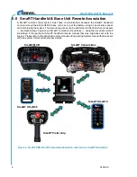
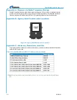
Page 12: ...can be performed in the field when necessary troubleshooting or replacing a SmaRT component for instance using the Associate method prescribed in the particular SmaRT handheld remote manual that was originally sent with the system Please refer to the handheld remote manual or Engineering System manual that was sent with the system for Associate process details Figure 9 SmaRT EBU xH24XF Associate I...

Page 13: ... 36mm High Impact Polymer 7 4mm 0 29 dia 5 63 center to center 143mm center to center 1 45lbs 0 66kg Outputs Inputs H Bridge Active Low 1V FET Form C Relay Analog Inputs Analog Outputs One 4A M1 M2 Sixteen M1 M16 digital inputs Eight Open Drain 2A per channel with current sense M1 M8 Eight Open Drain 4A per channel M9 M16 Two 8A per channel M17 M18 Four 0 10V M21 M24 Two 0 10V M19 M20 CAN Open Plu...

Page 14: ...ble 9 defines antennas antenna extensions and antenna kits available for the EBU xH24XF EXT base units Table 9 Compatible EBU xH 24XF 7773 External Antenna Details Part Cervis Ref No 900MHz IS BAND Swivel Antenna BB3 06 2 4GHz IS Band Swivel Antenna BB3 07 3 ft antenna extension cable J5 07 10 ft antenna extension cable J5 02 10 ft antenna cable J5 02 and external antenna BB3 06 EXT 10 900 10 ft a...

Page 15: ...ed at the factory Appendix E EBU xH24XF Cable Harness Options Table 10 EBU xH24XF Cable Harnesses Part Connector Colors Cable HN 1026 GRAY and GREEN Two 12 pin connectors 24 wire 90 inch total length Individually numbered 6 inch flying leads HN 1027 BROWN and BLACK Two 12 pin connectors 24 wire 90 inch total length Individually numbered 6 inch flying leads HN 1016 GRAY One 12 pin connector 12 wire...

Page 16: ...2 History Table Date Action By 1 10 18 1ST REVIEW GMS 1 15 18 2nd REVIEW MAM AMD edits GMS 1 15 18 Original Release GMS Visit our Web site at www cervisinc com 2018 Cervis Inc All rights reserved Content is subject to change without notice ...

Reviews: