background image


SmaRT 206 


U024.2-SmaRT_206_SYS-R 

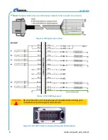
Note: Harness cable wires are individually marked on the insulator of each wire. 


Figure 8. Wiring Harness Cable 


Figure 9. Field Wiring Layout 

CAUTION 


Be sure the ends of all unused wires are insulated when making your 
connections to protect against short circuits. 


Figure 10. BU-206F Cable Connecter (Enhanced Pin Numbers)  

Summary of Contents for SmaRT 206

Page 1: ...2008 Cervis Inc 206 Remote Control System User Manual DN U024 2 SmaRT_206_SYS R...

Page 2: ...ce pursuant to Part 15 of the FCC Rules These limits are designed to provide reasonable protection against harmful interference in a residential installation This equipment generates uses and can radi...

Page 3: ...stallation 7 4 0 Using the SmaRT PTO 206 Handheld Remote 9 5 0 System Operation 10 5 1 Initial Use Instructions 10 6 0 Specifications 12 6 1 PTO 206 Handheld Remote 12 6 2 BU 206F Base Unit 13 List of...

Page 4: ...ority to operate the equipment Make sure that the machinery and surrounding area is clear before operating Do not activate the remote control system until certain that it is safe to do so Turn off the...

Page 5: ...t tight 5 water jetted from any direction on the enclosure shall have no harmful effects PTO Push to Operate Command broadcast only while a button is depressed The command ends when the button is rele...

Page 6: ...SmaRT 206 U024 2 SmaRT_206_SYS R iv This page is intentionally left blank...

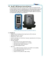
Page 7: ...that require remote operation Figure 1 PTO 206 Handheld Remote and BU 206F Base Unit 1 1 Features Rugged compact weatherproof high impact polymer IP65 enclosures Operating Temp 20 C to 55 C Storage Te...

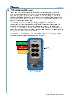
Page 8: ...handheld enclosure is constructed of rugged high impact polymer and a polycarbonate face plate securely sealed and attached by eight screws that is then overlaid with a durable attractively printed p...

Page 9: ...to a SmaRT handheld unit without the need to open either the remote or base unit case All controlled apparatus connections to the base unit are made using a single cable The base unit compact enclosur...

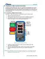
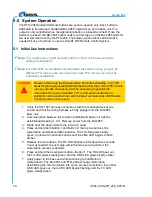
Page 10: ...held in your hand 3 Simultaneously press and hold the Association and Disassociation buttons see Figure 5 The TX LED glows steady green Figure 5 Handheld PTO Front Panel 4 Continue to hold both button...

Page 11: ...all previously established handheld remote links It will be necessary to perform the Association Procedure 1 4 1 above using each handheld to re establish communication links with the base unit 1 Rem...

Page 12: ...partment cover and lift the cover from the handheld 2 If installing batteries in an empty battery compartment install three fresh size AAA batteries Be sure to position the batteries as shown in Figur...

Page 13: ...t is left much to your discretion with the following guidelines Make sure that the configuration diagrams supplied with the system are available Keep them where they can be easily accessed when needed...

Page 14: ...y marked on the insulator of each wire Figure 8 Wiring Harness Cable Figure 9 Field Wiring Layout CAUTION Be sure the ends of all unused wires are insulated when making your connections to protect aga...

Page 15: ...e SmaRT PTO 206 Handheld Remote has six 6 push to operate buttons and three 3 diagnostic LEDs PTO buttons 1 and 2 have dual functions as described in Figure 11 Figure 11 PTO 206 Front Panel Output 2 A...

Page 16: ...ure Heading 1 4 1 using each handheld to re establish communication links with the base unit before the 206 Remote Control System can be used 1 Verify the HN 1001 harness connections with the controll...

Page 17: ...ates the output to which it is assigned When a PTO button is pressed its assigned base unit output is active and the base unit Out LED should glow green for as long as the output is active When the PT...

Page 18: ...55 C 40 F to 131 F Humidity 0 to 100 Radio Frequency 2405 2480MHz RF Signal 2mW License License free Modulation DSSS Antenna Internal Enclosure Dimensions mm 136 38 x 67 96 x 28 42 inches 5 37 x 2 68...

Page 19: ...Shock IEC60068 2 6 10Hz to 150Hz 1 0g peak acceleration 10 0g peak shock acceleration Radio Frequency 2405 2480MHz RF Signal 2mW License No license required Modulation DSSS Antenna Internal Enclosure...

Page 20: ...SmaRT 206 U024 2 SmaRT_206_SYS R 14 Cervis Inc Visit our Web site at www cervisinc com and are trademarks of CERVIS Inc 2008 Cervis Inc All rights reserved Content is subject to change without notice...

Page 21: ...Remote Control System 2008 Cervis Inc 15...

Reviews: