background image

10

model no. 060-1707-0  

4

5

6

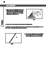
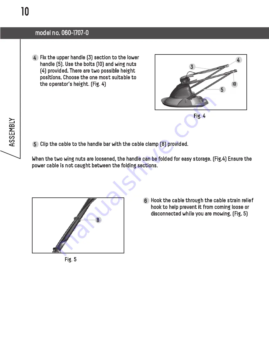
Fix the upper handle (3) section to the lower 
handle (5). Use the bolts (10) and wing nuts 
(4) provided. There are two possible height 
positions. Choose the one most suitable to 
the operator’s height. (Fig. 4)

Clip the cable to the handle bar with the cable clamp (8) provided.

When the two wing nuts are loosened, the handle can be folded for easy storage. (Fig.4) Ensure the 
power cable is not caught between the folding sections.

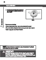
Hook the cable through the cable strain relief 
hook to help prevent it from coming loose or 
disconnected while you are mowing. (Fig. 5)

ASSEMBL

Y

4

8

3

5

10

Fig. 4

Fig. 5

Summary of Contents for 060-1707-0

Page 1: ... 060 1707 0 Instruction Manual IMPORTANT Read and follow all safety rules and operating instructions before using this product Electric Hover Mower 3084514 Conforms to UL STD 82 Certified to CSA STD C22 2 No 147 15 ...

Page 2: ...mbols 7 Know Your Hover Mover 8 Assembly 9 Operation 11 Maintenance 15 Troubleshooting 17 Exploded View 18 Parts List 19 Warranty 20 CONTENTS PRODUCT SPECIFICATIONS Electric Hover Mower Voltage 120 V 60 Hz Motor 11 A Motor Speed 8000 RPM Cutting path 11 1 2 29 cm Height adjustments 1 4 or 1 1 4 1 or 3 3 cm Weight 10 lb 8 oz 4 8 kg ...

Page 3: ... using the hover mower and after any impact check for signs of wear or damage and repair as necessary Never operate the hover mower with damaged guards or without the guards in place Keep hands and feet away from the cutting line at all times and especially when switching on the motor Always return the machine to its normal operating position before switching on Never fit metal cutting elements Ne...

Page 4: ...r footing and balance at all times Stay Alert Watch what you are doing Use common sense Do not operate appliance when you are tired or under the influence of drugs or alcohol MAINTENANCE After use disconnect the hover mower from the power source and check for damage When not in use store the hover mower out of the reach of children Electrical powered hover mowers should only be repaired by an auth...

Page 5: ... PARTS WHEN SERVICING THE HOVER MOWER TO AVOID INJURY DOUBLE INSULATION DOES NOT TAKE THE PLACE OF NORMAL SAFETY PRECAUTIONS WHEN OPERATING THIS HOVER MOWER TO AVOID ELECTROCUTION 1 Use only identical replacement parts when servicing a tool with double insulation Servicing should be performed by a qualified technician 2 Do not use in wet or damp areas or expose to rain ELECTRICAL INFORMATION DOUBL...

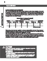
Page 6: ...l circuit for your tools This circuit should comprise a wire of at least 12 gauge and should be protected with a 15 A time delayed fuse Before connecting the motor to the power line make sure the switch is in the OFF position and the electric current is identical to that stamped on the motor nameplate Running at a lower voltage will damage the motor Minimum Gauge for Extension Cords AWG when using...

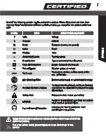
Page 7: ...in Minutes Time Alternating Current Type of current Direct Current Type or a characteristic of current Class II Construction Double insulated construction no No Load Speed Rotation speed at no load min Per Minute Revolutions strokes surface speed orbits etc per minute Wet Conditions Alert Do not expose to rain or use in damp locations Read The Operator s Manual To reduce the risk of injury user mu...

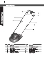
Page 8: ... lever 9 Retaining pin See page 9 3 Upper handle 10 Bolts See page 10 4 Handle fastening wing nuts 11 Cutting head See page 11 5 Lower handle 12 Fan See page 11 6 Safety lock off button 13 Plastic blade See page 14 7 Cable strain relief hook 14 Slot See page 15 KNOW YOUR HOVER MOVER 6 7 8 1 2 3 4 5 ...

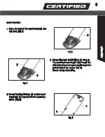
Page 9: ...Fig 2 Fig 3 Secure the lower handle 5 to the deck by rmly pushing a retaining pin 9 through the retaining holes on the deck and through the bottom end of the handle Fig 2 Repeat on the other side Ensure the upper handle 3 and the lower handle 5 are aligned correctly and move freely Fig 3 5 9 3 5 5 ...

Page 10: ...operator s height Fig 4 Clip the cable to the handle bar with the cable clamp 8 provided When the two wing nuts are loosened the handle can be folded for easy storage Fig 4 Ensure the power cable is not caught between the folding sections Hook the cable through the cable strain relief hook to help prevent it from coming loose or disconnected while you are mowing Fig 5 ASSEMBLY 4 8 3 5 10 Fig 4 Fig...

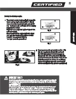
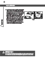
Page 11: ...g head 11 counterclockwise as illustrated Hold the cutting head 11 in the centre and remove as illustrated Hold the fan 12 in the centre and remove as illustrated Inspect for damage and clean as necessary before replacing the fan and the cutting head IMPORTANT Ensure the power cord is disconnected from the mains supply and wait until the cutting head has stopped rotating before adjusting the cutti...

Page 12: ...you want the higher setting 33 mm Turn the cutter head 11 the other way around with a larger space between the fan 12 and the cutting blades if you want the lower cutting height setting 10 mm Hold the fan 12 firmly and twist the cutting head 11 clockwise as illustrated Ensure it is securely locked into position IMPORTANT Ensure the power cord is disconnected from the mains supply and wait until th...

Page 13: ...fety lock off button 6 on the handle then activate the start stop switch lever 2 Release the lock off button 6 To switch off release the start stop switch lever 2 Start cutting once the mower has reached full speed WARNING After switching off the equipment the blade may continue to turn for several seconds Do not touch the moving blade There is a risk of serious injury NOTE There are two start sto...

Page 14: ...nd also adversely affect the mowing quality and the grass collection Switch off the motor before you carry out any inspections of the cutting head Remember that the cutting head will continue to turn for a few seconds after the motor has been switched off Never attempt to stop the cutting head The cutting system must be kept in good condition and inspected before and after use Switch off the motor...

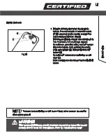
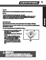
Page 15: ...solid object Always replace blades in pairs when worn or broken Carry out the following steps to change the plastic blades Disconnect from the mains electricity supply and wait until the cutting head 11 has stopped rotating Turn the mower over and rest it carefully on its side Push the plastic blade 13 towards the centre of cutting head 11 Fig 11 Lift the plastic blade away form cutting head If a ...

Page 16: ...side of the cutting head and pull into place Fig 12 2 IMPORTANT Ensure plastic cutters are correctly located Never fit a metal bar blade to this product If the blade has broken it will be difficult to take it off by hand or even may hurt your fingers so it is necessary to wear gloves or other protective equipment to prevent harming your fingers NOTE Plastic blades must be replaced in pairs to reta...

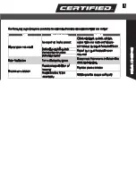
Page 17: ... cable wire and have any repairs carried out by a qualified electrician Defective on off switch Repair by a qualified technician required Worn carbon brushes Defective motor Poor floatation Fan is blocked by grass Disconnect from mains and clean the deck and the fan Excessive vibration Plastic blades broken or missing Replace plastic blades Plastic blades fitted incorrectly Fit the plastic blades ...

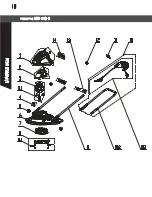
Page 18: ...18 model no 060 1707 0 EXPLODED VIEW ...

Page 19: ... pin 2 6 111023104 Deck Assembly 1 7 111022107 Fan Impeller 1 8 111022108 Blade Carrier Assembly 1 8 1 111022109 Blade 2 9 111023105 Lower Handle 2 10 111023106 Upper Handle Assembly with Switch box 1 10 1 111023107 Switch Box Assembly 1 10 2 111022114 Upper Handle 1 11 111005128 Cord retainer 1 12 111001111 Cable Clip 2 13 111023108 Upper Handle Twist lock Knob Assemby 2 14 111023109 Storage Box ...

Page 20: ... sandpaper bits fluids tune ups or adjustments e this warranty will not apply where damage is caused by repairs made or attempted by others i e persons not authorized by the manufacturer f this warranty will not apply to any product that was sold to the original purchaser as a reconditioned or refurbished product unless otherwise specified in writing g this warranty will not apply to any product o...

Page 21: ...MADE IN CHINA IMPORTED BY TRILEAF DISTRIBUTION TRIFEUIL TORONTO CANADA M4S 2B8 ...

Reviews: