background image


DF Touch 

Page 20 of 32 


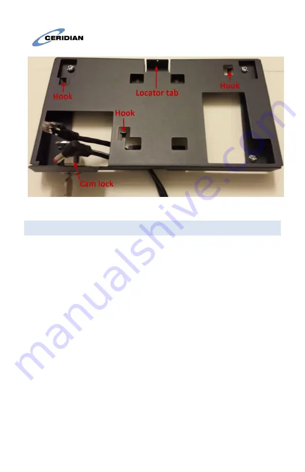
Figure 2: 

Wall-mount with cables 

10.2


Connecting and attaching the clock  

With the clock held close to the wall-mount, insert the cable plugs into 
the appropriate receptacles. Figures 3 and 4 show the clock with cables 
connected. 

With the cables connected, position the three hangers on the rear 
housing over and above the hooks on the wall mount, using the tab at 
the top of the clock as a guide. Then, push the clock down into the 
hooks. 

With the clock firmly on the hooks, rotate the key 90 degrees counter-
clockwise to secure the lock to the wall-mount. Finally, remove the key 
from the lock. 

Summary of Contents for Dayforce Touch Clock

Page 1: ...the limitation and liability of the manufacturer Read the entire manual carefully Read and save these instructions Follow all warnings and instructions specified within this document and or on the equ...

Page 2: ...in optimal condition by following all the instructions that are included within this manual and or marked on the product 3 HANDLING PRECAUTIONS Do not subject the touchscreen to mechanical shock e g...

Page 3: ...t that provides the pollution degree max 2 and over voltages category II non hazardous locations indoor only It is designed to be installed serviced and or repaired by service persons only service per...

Page 4: ...6 3 Environment Operating temperature 0 to 40 C 32 to 104 F Storage temperature 30 to 80 C 22 to 176 F Humidity 10 to 90 relative humidity non condensing 6 4 Power Supply Input Power Jack 24 VDC 5 0 7...

Page 5: ...Discharging battery 20 to 60 C 4 to 140 F 6 5 Operating System Android 4 0 4 ICS Android 6 0 1 Marshmallow Available Q4 2018 6 6 Application Programs Dayforce Clock Program Dayforce Self Service 6 7 E...

Page 6: ...erminal host and router Static IP addresses may also be assigned manually via the touch screen The terminal supports the use of DNS servers to convert host names to host IP addresses in both DHCP and...

Page 7: ...DF Touch Page 7 of 32 Ports for model A7 A8...

Page 8: ...s extra cost Fingerprint Biometric reader Barcode slot reader visible or infra red light Magnetic slot reader Proximity reader 125Khz or 13 5Mhz for HID Proxpoint iClass Mifare NFC 6 14 Barcode Reader...

Page 9: ...e Resolution 6 mils PCC 90 Print contrast ration 60 Bars must be centered 11mm from the edge of the card and should be 10mm high or more There must be at least 6mm white space on both sides of the bar...

Page 10: ...mount Weight about 4 4 lbs 2Kg with packaging 7 BATTERY PACK OPTIONAL A battery pack is not shipped with the clock but can optionally be added if requested To use the battery you must first plug it i...

Page 11: ...uch Clock warranty 8 1 L18650 2ACR Battery Instructions This product may be supplied with a rechargeable Lithium Ion battery The following are important safety instructions for using storing and dispo...

Page 12: ...in water expose to strong mineral oxides or heat the battery over 60 degrees Celsius Exposure to battery contents may be harmful In case of eye exposure flush with water for 15 minutes without rubbin...

Page 13: ...DF Touch Page 13 of 32 L18650 2ACR Battery Pack Place the metal clip over the battery as shown in the following figure Metal clip on battery pack...

Page 14: ...into the back of the terminal so that the metal clip is under the plastic tab as pictured in the following figure Inserting the battery Then snap it down so that the two cutouts on the side snap unde...

Page 15: ...DF Touch Page 15 of 32 Insert the battery wire connector onto the pins as shown Inserting the wire connectors Battery connected...

Page 16: ...Charging and Forming Power the unit from the AC DC wall adapter or PoE New clocks will automatically form the batteries The forming procedure will fully charge the battery over a period of about 24 h...

Page 17: ...utton if necessary to shut it down Reset switch location 9 CAMERA USE APPLICATION NOTES The following best practices are recommended for recording punches using camera validation The puncher s face sh...

Page 18: ...ending on the option selected 10 INSTALLATION INSTRUCTIONS The DF Touch Clock has two parts the clock and the wall mount The Clock is shipped in a cardboard carton together with the wall mount keys fo...

Page 19: ...s top edge 48 inches from the ground If the camera feature will be used or if wheelchair access is not required install the wall mount with its top edge 56 inches from the ground If the wall mount is...

Page 20: ...3 and 4 show the clock with cables connected With the cables connected position the three hangers on the rear housing over and above the hooks on the wall mount using the tab at the top of the clock a...

Page 21: ...DF Touch Page 21 of 32 Figure 3 Clock with cables connected and wall mount Figure 4 Clock with cables connected and partial wall mount...

Page 22: ...kwise 90 degrees You can then lift the clock off the hooks and detach the cables 10 4 Note re Power Supply Clocks are supplied with both an external low current power pack which delivers 24V DC and Po...

Page 23: ...manual by using the static IP addressing function provided Clients protected by a Firewall must allow the clocks to communicate through ports TCP 443 and TCP 80 Inter clock communications uses port TC...

Page 24: ...Dayforce Touch Clock Guide to view the IP address If there is no IP address please check the following that the Ethernet cable is connected to a live port and that the DHCP server is functioning or if...

Page 25: ...there is an issue preventing access to the Ceridian server 1 If you get the Service page as described in the previous step but the clock is still not connecting yellow status icon then please send th...

Page 26: ...no battery backup installed temporarily remove external power from clock 14 CLOCK INFORMATION AND SETUP STATIC IP 1 On the home screen touch and hold the Welcome to Dayforce HCM message After a few s...

Page 27: ...nfiguration 2 Clear the Use Dynamic IP Address check box 3 Type the following information into the appropriate fields o IPv4 Address o Subnet Mask o Default Gateway o Primary DNS Server o Secondary DN...

Page 28: ...mmunications However there is no guarantee that interference will not occur in a particular installation If this equipment causes harmful interference to radio or television reception which can be det...

Page 29: ...ilisateur de l appareil doit accepter tout brouillage radio lectrique subi m me si le brouillage est susceptible d en compromettre le fonctionnement CAN ICES 3 B NMB 3 B This equipment complies with I...

Page 30: ...mitter Modules o FCC ID RYK WUBR170GNM o IC ID 6158A WUBR170GNM OR o FCC ID Z64 WL18SBMOD o IC ID 4511 WL18SBMOD o FCC ID 2AJLM UNT1422 o IC ID 21879 UNT1422 Model DF Touch W Contains Transmitter Modu...

Page 31: ...DF Touch Page 31 of 32...

Page 32: ...Shakopee Road Minneapolis 55425 MN For support call 1 866 748 7066 Canada Ceridian Canada Ltd 125 Gary Street Winnipeg R3C 3P2 For support call 1 877 237 4342 Europe Dayforce Europe Ltd Sonas 3 King s...

Reviews: