


5
13. Connect the four wires from the motor to the automation
adapter.
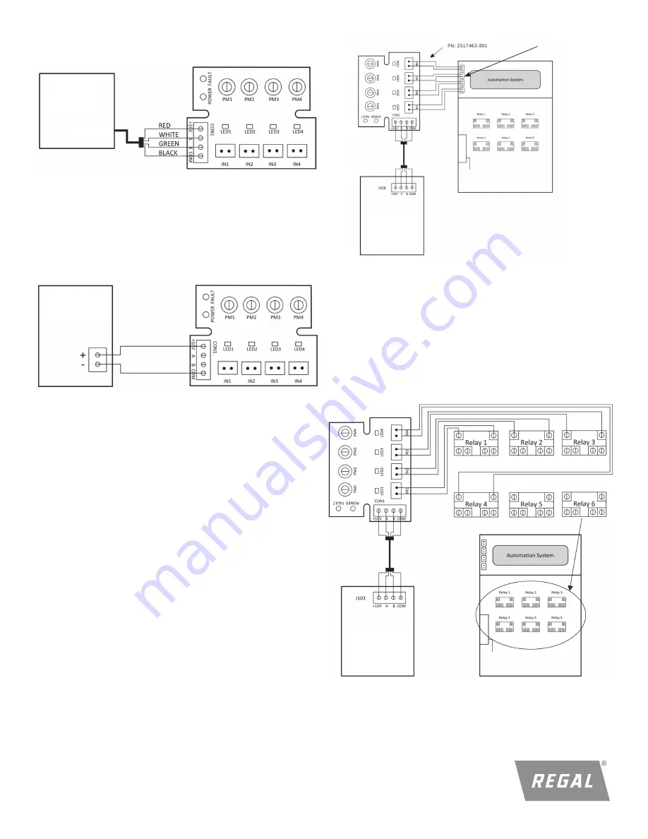
Figure 17: Motor connected to adapter
Figure 18:
Automation adapter connected to alternate power source
VGreen
®
Motor
Alternate
Power Source
J103
5.0 CONNECTING TO AN ALTERNATE POWER
SOURCE:
If you choose not to power the automation adapter from the
VGreen
®
motor (J103 low voltage power supply), the automation
adapter can be powered from any 10-14 VDC alternate power
supply.
6.0 CONNECTING TO AN AUTOMATION SYSTEM
WARNING! SHOCK HAZARD
Access to the connections referenced in the diagrams
and instructions below could be in close proximity to main
connections which carry line voltage capable of causing personal
injury or damaging the equipment if contact is made. Power
should be turned off when accessing these areas. Failure to take
these precautions could result in serious injury or death.
NOTE:
User may use a minimum of 1 and a maximum of 4 inputs
to the automation adapter.
WARNING! SHOCK HAZARD
Failure to connect the automation adapter to the automation
system wighout using correct polarity may result in damage to
the automation adapter and automation system.
6.1 USING AUTOMATION SYSTEM OUTPUT CONNECTORS
Connect IN1 to AUX1 or any output from the automation
system. Repeat this for IN2, IN3, and IN4 using different
automation system outputs for each input.
Figure 19:
Automation adapter connected to automation system using
the automation system outputs
OUTPUTS
(i.e. AUX1)
VGreen
®
Motor
6.2 USING AUTOMATION SYSTEM RELAYS
6.21 Connecting to input (i.e. low voltage) side of relays
Connect IN1 to Relay 1 or any relay from the automation
system. Repeat this for IN2, IN3, and IN4 using different
automation system relays for each input.
Figure 20:
Automation adapter connected to automation system using
the automation system relays
VGreen
®
Motor


