background image

5

14

Sets the number of seconds for which keystrokes remain valid. 
This ensures that if a partial code has been entered, it is wiped 
out of the keypad buffer after a preset time, and must be re-
entered in its entirety. The clearing of the keypad buffer is 
indicated by the keypad back light changing from bright (active) 
to dim (standby). Default wipeout timer = 15 seconds. 

Enter the following keystrokes:

1. Enter Program mode   Master Code  
2. Select Wipeout menu 5 #
3. Enter Wipeout time

Seconds #

4. Exit Program mode

#

Notes:

!

If the Wipeout time is set to 0, key wipeout will be disabled.
 

IMPORTANT

Disabling the key wipeout timer will:

!

Compromise the security of the system.

!

Cause a code entry to be incorrectly recognised as a 
WRONG CODE if an incomplete code was previously 
entered.

!

If key wipeout is disabled, the keypad back light will remain 
in bright mode.

Setting the key wipeout timer

INDICATOR LED's

Summary of Contents for SMART GUARD air

Page 1: ...GUARD OPERATING INSTRUCTIONS CENTURION THE AUTOMATIC CHOICE ...

Page 2: ...ess Address 4 Enter access code Code Default master code 1234 Example KwikLearn access code 93245 into address 25 Master code 1234 Enter program mode 1 2 3 4 Select KwikLearn 0 Enter user address 2 5 Enter access code 9 3 2 4 5 The following KwikLearn procedure and connection diagram will enable you to start using your SmartGUARD systemrightaway Additionalproceduresareexplainedlaterinthismanual IN...

Page 3: ...2V AC 220V AC OUTPUT 1 DOOR STRIKE FREE EXIT POWER SUPPLY 12 24V DC AC IMPORTANT IF YOUR SUPPLY VOLTAGE TO THE SMART GUARD EXCEEDS 24V AC OR 30V DC FIT THE SUPPLIED 150R RESISTOR IN SERIES WITH THE SUPPLYWIREASSHOWN DO NOT USE THIS PRODUCT WITH SUPPLY VOLTAGES GREATER THAN 30VACOR40VDC ...

Page 4: ...please be aware of the following Indicates a lit LED Indicates optional entries The factory default master code 1 2 3 4 is used throughout this manual as an example only Refer to page 5 for instructions on howtochangethemastercode Indicates a particular key to be pressed on the keypad by the user How to Follow the Procedures If you intend using the DURESS security parameter Page 16 ensure that no ...

Page 5: ...parameters 12 Setting the key wipeout timer 14 Setting the security parameters 16 Backing up the unit 19 Restoring the unit 20 Defaulting the unit 21 Defaulting the Master Code 21 Defaulting the System Parameters 21 Typical mounting instructions 22 Fitting the optional anti tamper switch 24 Typical connection diagram 25 Glossary 26 Installation Information 27 1 ...

Page 6: ...l free relay contact capable of switching up to 3A at 50V Both normally closed and normally open contacts are available The second and third outputs are open collector channels capable of directly switching any negative triggered equipment or an external relay The output channels can be set as pulsed or latching with pulse times adjustable in one second increments between one second and four minut...

Page 7: ...nal pushbutton giving free exit capability Once programmed the system can be backed up onto the optional CP108 backup module This allows the system to be easily restored if required An optional independent tamper switch can be fitted to provide a contact indicating if the unit has been forcedopen orremovedfromitsmountings ...

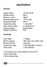
Page 8: ...Open collector rating 2 x 50mA 24V Housing material Polycarbonate Degree of protection IP55 Functional Code length 1 10 Digits Memory capacity 1000 unique non volatile codes Memory retention 200 years Output pulse range 1 255s adjustable or latched Token codes 1 254 activations 1 All outputs active Smart Switches on Ch2 Ch3 2 Non condensing 3 Non inductive load Specifications ...

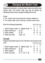
Page 9: ...ways be stored at address 0 The master code can be used as a normal access code Enter the following keystrokes 1 Enter Program mode Master Code 2 Select KwikLearn 0 3 Enter address 0 4 Enter new code Code Example Replace the default master code 1234 with a new master code 3781 1 Enter Program mode Master Code 2 Select KwikLearn 0 3 Enter address 0 4 Enter new code INDICATOR LED s INDICATOR LED s 3...

Page 10: ...ct outputs Output 6 Assign outputs 7 Enter access limit Accesses 8 Exit Add menu 9 Exit Program mode Repeat step 5 for additional outputs Repeat steps 3 7 for additional users Notes If no output is specified the relay output is selected If the number of access are not specified in step 7 unlimited access is set Care must be taken to ensure the desired access limit is correctly applied NB If unlimi...

Page 11: ...nter access limit Exit Add menu Exit Program mode Example Add access code 93523 into address 10 Code must operate outputs1and3 Codeisvalidfor2uses Mastercode 1234 Enter Program mode 1 2 3 4 Select Add menu 1 Enter user address 1 0 Enter access code 9 3 5 2 3 Select outputs 1 3 Assign Outputs Enter access limit 2 Exit Add menu Exit Program mode INDICATOR LED s INDICATOR LED s ...

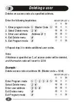
Page 12: ... 5 Exit Program mode Repeat step 3 to delete additional user codes Note If Address is specified as 0 all access codes will be deleted and the master code will revert to 1234 Example Delete access code at address 99 Master code 1234 Enter Program mode 1 2 3 4 Select Delete menu 2 Enter user address 9 9 Exit Delete menu Exit Program mode Deleting a user INDICATOR LED s INDICATOR LED s ...

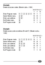
Page 13: ...te menu 2 Enter user address 0 Exit Delete menu Exit Program mode Example Delete access code at address 54 and 87 Master code 1234 Enter Program mode 1 2 3 4 Select Delete menu 2 Enter user address 5 4 Enter user address 8 7 Exit Delete menu Exit Program mode INDICATOR LED s INDICATOR LED s ...

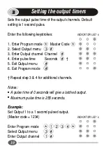
Page 14: ...el 4 Enter pulse time Seconds 5 Exit Output menu 6 Exit Program mode Repeat step 3 4 for additional channels Notes A pulse time of 0 seconds will give a latched output Maximum pulse time is 255 seconds Example Set Output 1 to a 1 second pulsed output Master code 1234 Enter Program mode 1 2 3 4 Select Output menu 3 Enter Output channel 1 3 10 Setting the output timers INDICATOR LED s INDICATOR LED ...

Page 15: ... Output 2 to 5s pulse and Output 3 to 1s pulse Master code 1234 Enter Program mode 1 2 3 4 Select Output menu 3 Enter Output channel 1 Enter pulse time 0 Enter Output channel 2 Enter pulse time 5 Enter Output channel 3 Enter pulse time 1 Exit Output menu Exit Program mode INDICATOR LED s ...

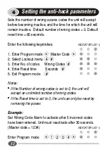
Page 16: ...4 3 Enter No of codes Wrong Codes 4 Enter Reset time Seconds 5 Exit Program mode Notes If the Number of wrong codes is set to 0 the unit will accept an unlimited number of wrong codes If the Reset time is set to 0 the unit can only be reset by removing the power Example Set Wrong Code Alarm to activate after 5 incorrect codes have been entered Unit must reactivate after 30 seconds Master code 1234...

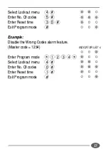
Page 17: ... Of codes 5 Enter Reset time 3 0 Exit Program mode Example Disable the Wrong Codes alarm feature Master code 1234 Enter Program mode 1 2 3 4 Select Lockout menu 4 Enter No Of codes 0 Enter Reset time 1 Exit Program mode INDICATOR LED s ...

Page 18: ...peouttimer 15seconds Enter the following keystrokes 1 Enter Program mode Master Code 2 Select Wipeout menu 5 3 Enter Wipeout time Seconds 4 Exit Program mode Notes If the Wipeout time is set to 0 key wipeout will be disabled IMPORTANT Disabling the key wipeout timer will Compromise the security of the system Cause a code entry to be incorrectly recognised as a WRONG CODE if an incomplete code was ...

Page 19: ...34 Enter Program mode 1 2 3 4 Select Wipeout menu 5 Enter Wipeout time 1 5 Exit Program mode Example Disable the key wipeout time Master code 1234 Enter Program mode 1 2 3 4 Select Wipeout menu 5 Enter Wipeout time 0 Exit Program mode INDICATOR LED s INDICATOR LED s ...

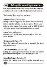
Page 20: ...nder duress E g Access code is 1234 Entering 1235givesaccess butalsoactivatesthealarmchannel Alarm Default off Pressing the and keys simultaneously activates the alarm channel Wrongcodes Default off When the number of wrong codes is exceeded the alarm channelisactivated Anti Default feature Default off Setting this feature prevents the master code and system parametersfrombeingresetbythedefaulting...

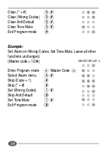
Page 21: ...ode Master Code Select Alarm menu 6 Set Code 1 0 or 1 Set 0 or 1 Set Wrong Codes 0 or 1 Set Anti Default 0 or 1 Set Tone Mute 0 or 1 Exit Program mode Note 0 turns function off 1 turns function on leaves function unchanged Example Enable alarm on Code 1 Clear all other functions Master code 1234 Enter Program mode Master Code Select Alarm menu 6 Set Code 1 1 INDICATOR LED s INDICATOR LED s ...

Page 22: ...Exit Program mode Example Set Alarm on Wrong Codes Set Tone Mute Leave all other functions unchanged Master code 1234 Enter Program mode Master Code Select Alarm menu 6 Skip Code 1 Skip Set Wrong Codes 1 Skip Anti Default Set Tone Mute 1 Exit Program mode INDICATOR LED s ...

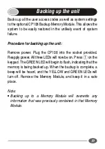
Page 23: ... into the socket provided Reapply power All three LEDs will now be on Press 1 on the keypad The GREEN LED will begin to flash indicating that the memory is being backed up When the backup is complete a beep will be heard and the YELLOW and GREEN LEDs will turn off Remove the Memory Module and keep it in a safe place Note Backing up to a Memory Module will overwrite any information that was previou...

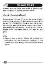
Page 24: ...Press 3 on the keypad The YELLOW LED will begin to flash indicating that the memory is being restored When the restore is complete a beep will be heard and the YELLOW and GREEN LEDs will turn off Remove the Memory Module and keep it in a safe place Note Restoring from a Memory Module will overwrite any information that was previously contained in the SmartGUARD unit In addition the master code wil...

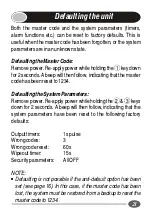
Page 25: ...codehasbeenresetto1234 DefaultingtheSystemParameters Remove power Re apply power while holding the 2 3 keys down for 2 seconds A beep will then follow indicating that the system parameters have been reset to the following factory defaults Outputtimers 1spulse Wrongcodes 3 Wrongcodereset 60s Wipeouttimer 15s Securityparameters AllOFF NOTE Defaulting is not possible if the anti default option has be...

Page 26: ...to separate cover and back panel 3 Fix the self adhesive rubber pads into the recesses provided on the rearpanel 4 Attach the rear panel to the mounting surface gooseneck with the supplied mounting screws provided Be sure to seal all mountings with silicone sealant 3 4 SELF ADHESIVE RUBBER PADS MOUNTING SCREW 22 Typical Mounting Instructions 2 1 ...

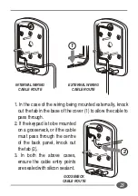
Page 27: ...le to passthrough 2 If the keypad is to be mounted on a gooseneck or if the cable must pass through the centre of the back panel knock out thetab 2 3 In both the above cases ensure the cable entry points aresealedwithsiliconsealant 23 GOOSENECK CABLE ROUTE INTERNAL WIRING CABLE ROUTE EXTERNAL WIRING CABLE ROUTE 1 2 ...

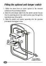
Page 28: ...nt contactsontheanti tamperswitch 2 Slide the anti tamper switch into the switch carrier Ensure that the retaining pins in the switch carrier pass through the matchingholesintheswitch 3 Slide the switch and carrier assembly into the grooves providedinthekeypad cover 3 2 1 TO 3rd PARTY ALARM SYSTEM ...

Page 29: ...OM TRG POWER SUPPLY 12 24V DC AC _ 12V AC 220V AC 1 2 3 4 5 6 7 8 9 OUTPUT 1 OUTPUT 2 DOOR STRIKE FREE EXIT IMPORTANT IF YOUR SUPPLY VOLTAGE TO THE SMART GUARD EXCEEDS 24V AC OR 30V DC FIT THE SUPPLIED 150R RESISTOR IN SERIES WITH THE SUPPLYWIREASSHOWN DO NOT USE THIS PRODUCT WITH SUPPLY VOLTAGES GREATER THAN 30VACOR40VDC ...

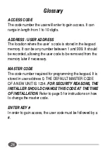
Page 30: ...uld be recorded allowing the user code to be removed from the memory later if necessary MASTER CODE The code number required for programming the keypad It is stored in user address 0 THE DEFAULT MASTER CODE OF A NEW UNIT IS 1234 FOR SECURITY REASONS THE INSTALLER SHOULD CHANGE THIS CODE AT THE TIME OF INSTALLATION Refer to page 5 for instructions on how to change the master code ENTER KEY In order...

Page 31: ...deandwhichoutput willbeactivatedbythataddress The supplied Address Register will record the first 500 addresses from 0 to 499 Should you require a second Address Register to record the next 500 addresses i e address 500 to 999 please contact your nearest CENTURIONSYSTEMSbranchordistributor KEEP THE ADDRESS REGISTER IN A SECURE PLACE 27 Installation Information Master Code Output 1 to Output 2 to O...

Page 32: ...Randburg SOUTH AFRICA Tel 27 0 11 699 2400 Fax 27 0 11 704 3412 www centsys co za email sales centsys co za info centsys co za Centurion Systems reserves the right to change any product without prior notice Represented in your area by CENTURION THE AUTOMATIC CHOICE ...

Reviews: