INSPECTION, MAINTENANCE, AND CLEANING
1.
Before each use, inspect the general condition of the Air Tank. Check the Air
Tank for loose connections and joints, cracked, bent, or broken parts, damaged
Air Hose, damaged Tank, and any other condition that may affect the safe opera-
tion of the Air Tank. If a problem occurs, have the problem corrected before
further use. Do not use damaged equipment.
2.
Daily: Slowly open the Drain Valve Assembly (1) by turning its Knob
counter-
clockwise, and allow all moisture to drain from the Tank (15). Next, close the
Drain Valve Assembly by turning its Knob
clockwise. Then, refill the Air Tank to
its maximum 125 PSI operating pressure rating.
3.
When cleaning, use only water and a mild detergent. Then dry. Do not use
cleaners that are combustible or corrosive.
SKU 91064
PAGE 7
PLEASE READ THE FOLLOWING CAREFULLY
THE MANUFACTURER AND/OR DISTRIBUTOR HAS PROVIDED THE PARTS LIST AND ASSEMBLY DIAGRAM IN
THIS MANUAL AS A REFERENCE TOOL ONLY. NEITHER THE MANUFACTURER OR DISTRIBUTOR MAKES
ANY REPRESENTATION OR WARRANTY OF ANY KIND TO THE BUYER THAT HE OR SHE IS QUALIFIED TO
MAKE ANY REPAIRS TO THE PRODUCT, OR THAT HE OR SHE IS QUALIFIED TO REPLACE ANY PARTS OF
THE PRODUCT. IN FACT, THE MANUFACTUER AND/OR DISTRIBUTOR EXPRESSLY STATES THAT ALL
REPAIRS AND PARTS REPLACEMENTS SHOULD BE UNDERTAKEN BY CERTIFIED AND LICENSED TECHNI-
CIANS, AND NOT BY THE BUYER. THE BUYER ASSUMES ALL RISK AND LIABILITY ARISING OUT OF HIS OR
HER REPAIRS TO THE ORIGINAL PRODUCT OR REPLACEMENT PARTS THERETO, OR ARISING OUT OF HIS
OR HER INSTALLATION OF REPLACEMENT PARTS THERETO.
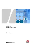
PARTS LIST
Part
#
Description
Qty.
Part
#
Description
Qty.
1
Drain Valve Assembly
2
9
Rod
1
1.1
Retaining Ring
2
10
Seal Washer
1
1.2
Air Outlet Knob
2
11
Core
1
1.3
Nut
2
12
Air Inlet Connector
1
1.4
O-Ring
2
13
Valve Body
1
1.5
Rod
2
14
Pressure Gauge
1
1.6
Base
2
15
Tank
1
2
Cover
1
16
Handle Grip
2
3
Core
1
17
Handle
2
4
Seal Washer
1
18
Wheel
2
5
Air Hose
1
19
Bearing
2
6
Safety Release Valve
1
20
Washer
4
7
Nut
1
21
Retaining Ring
2
8
Spring
1
22
Bolt
2