background image

Page 4

For technical questions, please call 1-800-444-3353.

SKU 44505

USE RIGHT TOOL. Don’t force tool or 

8. 

attachment to do a job for which it was 
not designed.

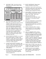
recOMMenDeD MiniMuM Wire 

gauge FOr eXtensiOn cOrDs 

(120 VOlt)

naMePlate 

aMPeres

(at full load)

eXtensiOn cOrD 

length

25’

50’

100’

150’

0 – 6

18

16

16

14

6.1 – 10

18

16

14

12

10.1 – 12

16

16

14

12

12.1 – 16

14

12

Do not use.

table a

USE PROPER EXTENSION CORD. 

9. 

Make sure your extension cord is in good 
condition. When using an extension 
cord, be sure to use one heavy enough 
to carry the current your product will 
draw. An undersized cord will cause a 
drop in line voltage resulting in loss of 
power and overheating. 


Table A shows 

the correct size to use depending on 
cord length and nameplate ampere 
rating. If in doubt, use the next heavier 
gauge. The smaller the gauge number, 
the heavier the cord.

WEAR PROPER APPAREL. Do not wear 

10. 

loose clothing, gloves, neckties, rings, 
bracelets, or other jewelry which may get 
caught in moving parts. Nonslip footwear 
is recommended. Wear protective hair 
covering to contain long hair.

ALWAYS USE SAFETY GLASSES. Also 

11. 

use face or dust mask if cutting operation 
is dusty. Everyday eyeglasses only have 
impact resistant lenses, they are NOT 
safety glasses.

SECURE WORK. Use clamps or a vise 

12. 

to hold work when practical. It’s safer 
than using your hand and it frees both 
hands to operate tool.

DON’T OVERREACH. Keep proper 

13. 

footing and balance at all times.

MAINTAIN TOOLS WITH CARE. Keep 

14. 

tools sharp and clean for best and safest 
performance. Follow instructions for 
lubricating and changing accessories.

DISCONNECT TOOLS before servicing; 

15. 

when changing accessories, such as 
blades, bits, cutters, and the like.

REDUCE THE RISK OF 

16. 

UNINTENTIONAL STARTING. Make 
sure switch is in off position before 
plugging in.

USE RECOMMENDED ACCESSORIES. 

17. 

Consult the owner’s manual for 
recommended accessories. The use of 
improper accessories may cause risk of 
injury to persons.

NEVER STAND ON TOOL. Serious 

18. 

injury could occur if the tool is tipped 
or if the cutting tool is unintentionally 
contacted.

CHECK DAMAGED PARTS. Before 

19. 

further use of the tool, a guard or other 
part that is damaged should be carefully 
checked to determine that it will operate 
properly and perform its intended 
function – check for alignment of moving 
parts, binding of moving parts, breakage 
of parts, mounting, and any other 
conditions that may affect its operation. 
A guard or other part that is damaged 
should be properly repaired or replaced.

DIRECTION OF FEED. Feed work into 

20. 

a blade or cutter against the direction of 
rotation of the blade or cutter only.

NEVER LEAVE TOOL RUNNING 

21. 

UNATTENDED. TURN POWER OFF. 
Don’t leave tool until it comes to a 
complete stop.

Summary of Contents for CENTRAL MACHINERY 44505

Page 1: ...rved No portion of this manual or any artwork contained herein may be reproduced in any shape or form without the express written consent of Harbor Freight Tools Diagrams within this manual may not be drawn proportionally Due to continuing improvements actual product may differ slightly from the product described herein Tools required for assembly and service may not be included For technical ques...

Page 2: ...s for putting into use 8 Assembly Mounting 8 Operating Instructions 10 Tool Set Up 10 Work Piece and Work Area Set Up 10 General Operating Instructions 11 Maintenance And Servicing 12 Cleaning Maintenance and Lubrication 12 Troubleshooting 14 Parts Lists and Diagrams 15 Head Assembly Parts List 15 Head Assembly Diagram 16 Parts List and Diagram A Pulley and Spindle 17 Parts List and Diagram B Chuc...

Page 3: ... symbol indicates a hazardous situation which if not avoided could result in minor or moderate injury NOTICE is used to address practices not related to personal injury CAUTION without the safety alert symbol is used to address practices not related to personal injury General Tool Safety Warnings WARNING Read all safety warnings and instructions Failure to follow the warnings and instructions may ...

Page 4: ...or a vise 12 to hold work when practical It s safer than using your hand and it frees both hands to operate tool DON T OVERREACH Keep proper 13 footing and balance at all times MAINTAIN TOOLS WITH CARE Keep 14 tools sharp and clean for best and safest performance Follow instructions for lubricating and changing accessories DISCONNECT TOOLS before servicing 15 when changing accessories such as blad...

Page 5: ...he electric cord or plug is necessary do not connect the equipment grounding conductor to a live terminal Check with a qualified electrician or 4 service personnel if the grounding instructions are not completely understood or if in doubt as to whether the tool is properly grounded Use only 3 wire extension cords that 5 have 3 prong grounding plugs and 3 pole receptacles that accept the tool s plu...

Page 6: ...lica from bricks and cement or other masonry products Arsenic and chromium from chemically treated lumber Your risk from these exposures varies depending on how often you do this type of work To reduce your exposure to these chemicals work in a well ventilated area and work with approved safety equipment such as those dust masks that are specially designed to filter out microscopic particles Calif...

Page 7: ...od supply to the hands and fingers increasing the risk of vibration related injury Wear suitable gloves to reduce the 3 vibration effects on the user Use tools with the lowest vibration when 4 there is a choice between different processes Include vibration free periods each day 5 of work Grip tool as lightly as possible while still 6 keeping safe control of it Let the tool do the work To reduce vi...

Page 8: ...itch of the tool to its OFF position and unplug the tool from its electrical outlet before assembling or making any adjustments to the tool Note For additional information regarding the parts listed in the following pages refer to the Assembly Diagram near the end of this manual Assembly Mounting Note Assembly hardware is located in separate bags boxes Position the 1 Base C4 on a level and sturdy ...

Page 9: ...8 Thoroughly clean the tapered hole in the a Chuck and the Spindle Shaft B7 of all dirt grease oil and protective coatings paint thinner may be necessary Slide the Chuck onto the Spindle Shaft b Turn the Chuck sleeve clockwise and c open the jaws completely Tap the nose of the Chuck lightly with d a piece of wood to securely set the Chuck Screw C6 11 Verify that the Table C7 is square 90 degrees t...

Page 10: ...wn until they 5 touch the Feed Wheel stop Tilting the Table Loosen Screw C6 under the Table 1 assembly with a wrench Rotate the Table to the desired angle 2 The scale can be used to approximate the angle Retighten the Screw 3 Work Piece and Work Area Set Up Designate a work area that is clean and 1 well lit The work area must not allow access by children or pets to prevent distraction and injury R...

Page 11: ...or workpiece alignment adjustments Plug the Power Cord 33 into an 6 electrical outlet Insert the Switch Key 24 into the 7 Locking Switch 21 Warning Wear an ANSI approved full face shield while drilling Push the Switch up to turn the Motor ON 8 Pull down on the Feed Knob and slowly 9 drill the hole into the workpiece Warning If the drill bit grabs and spins the workpiece do not attempt to stop the ...

Page 12: ... Removing the Chuck and Spindle Shaft During this procedure refer to the Chuck and Spindle Assembly Drawing Pull the Feed Wheel counterclockwise 1 and hold the Chuck at a depth of three inches Align the key holes in the Spindle Shaft 2 B7 and the Quill Tube B3 by turning the Chuck by hand Insert a Wedge Drift Key not supplied 3 into the key holes Place a bundled cloth or basket below 4 the Chuck t...

Page 13: ...ing Retainer 27 about 1 8 inch Hex Nuts 30 Spring Cap 29 Notch Hex Nuts 31 Pointer 32 5 Turn the screwdriver counterclockwise and engage the next Spring Cap notch Leave the screwdriver in place Tighten the inner Hex Nut just enough 6 to engage the notch If this Hex Nut is too tight it will restrict up and down Chuck Spindle movement Loosen and screw the Hex Nuts 31 to 7 the top of the Stop Rod B12...

Page 14: ...cessory dull or damaged 3 Blocked motor housing vents 4 Motor being strained by long or 5 small diameter extension cord Allow machine to work at its own rate 1 Check and correct accessory to table alignment 2 Keep cutting accessories sharp Replace as 3 needed Wear ANSI approved safety goggles and NIOSH 4 approved dust mask respirator while blowing dust out of motor using compressed air Eliminate u...

Page 15: ...ith Cover Record Product s Serial Number Here Note If product has no serial number record month and year of purchase instead Note Some parts are listed and shown for illustration purposes only and are not available individually as replacement parts PLEASE READ THE FOLLOWING CAREFULLY The manufacturer and or distributor has provided the parts list and assembly diagram in this manual as a reference ...

Page 16: ...Page 16 For technical questions please call 1 800 444 3353 SKU 44505 Head Assembly Diagram 35 36 37 38 39 40 ...

Page 17: ...r Parts List and Diagram A Pulley and Spindle Part Description A1 Bushing Rubber A2 Knob A3 Screw Pan Hd M5x0 8 12 A4 Belt V5 5 16x26 A5 Guard with Labels A6 Screw washer Hd M6x10 16 A7 Ring Retaining A8 Bearing Ball 17 mm A9 Spacer A10 Insert Pulley A11 Pulley Spindle A12 Nut Pulley A13 Clamp Cord A14 Screw Pan Hd M5x0 8 16 A15 Washer Foam ...

Page 18: ...this drawing add a B prefix to the part number Parts List and Diagram B Chuck and Spindle Shaft Part Description B1 Gasket Quill B2 Bearing Ball 12 mm B3 Tube Quill B4 Screw Pan M5x0 8 20 B5 Collar Stop B6 Ring Retaining B7 Shaft Spindle B8 Chuck B10 Nut Hex M6x1 0 B11 Nut Hex M5x0 8 B12 Stop Rod ...

Page 19: ...5 When ordering a part from this drawing add a C prefix to the part number Parts List and Diagram C Base and Table Part Description C1 Support Table with Scale C2 Support Lock Handle C3 Tube Support C4 Base C5 Screw Hex Hd M8x1 25 20 C6 Screw Hex Hd 1 2 12x7 8 C7 Table ...

Page 20: ...ncidental or consequential damages so the above limitation of exclusion may not apply to you This warranty is expressly in lieu of all other warranties express or implied including the warranties of merchantability and fitness To take advantage of this warranty the product or part must be returned to us with transportation charges prepaid Proof of purchase date and an explanation of the complaint ...

Reviews: