Central Machinery 63469 Owner'S Manual & Safety Instructions Download Page 26

Page 26

For technical questions, please call 1-888-866-5797.

Item 63469 


S

AFET

y

Op
ERA

TION

M

AINTENAN

c

E

S

ETU

p

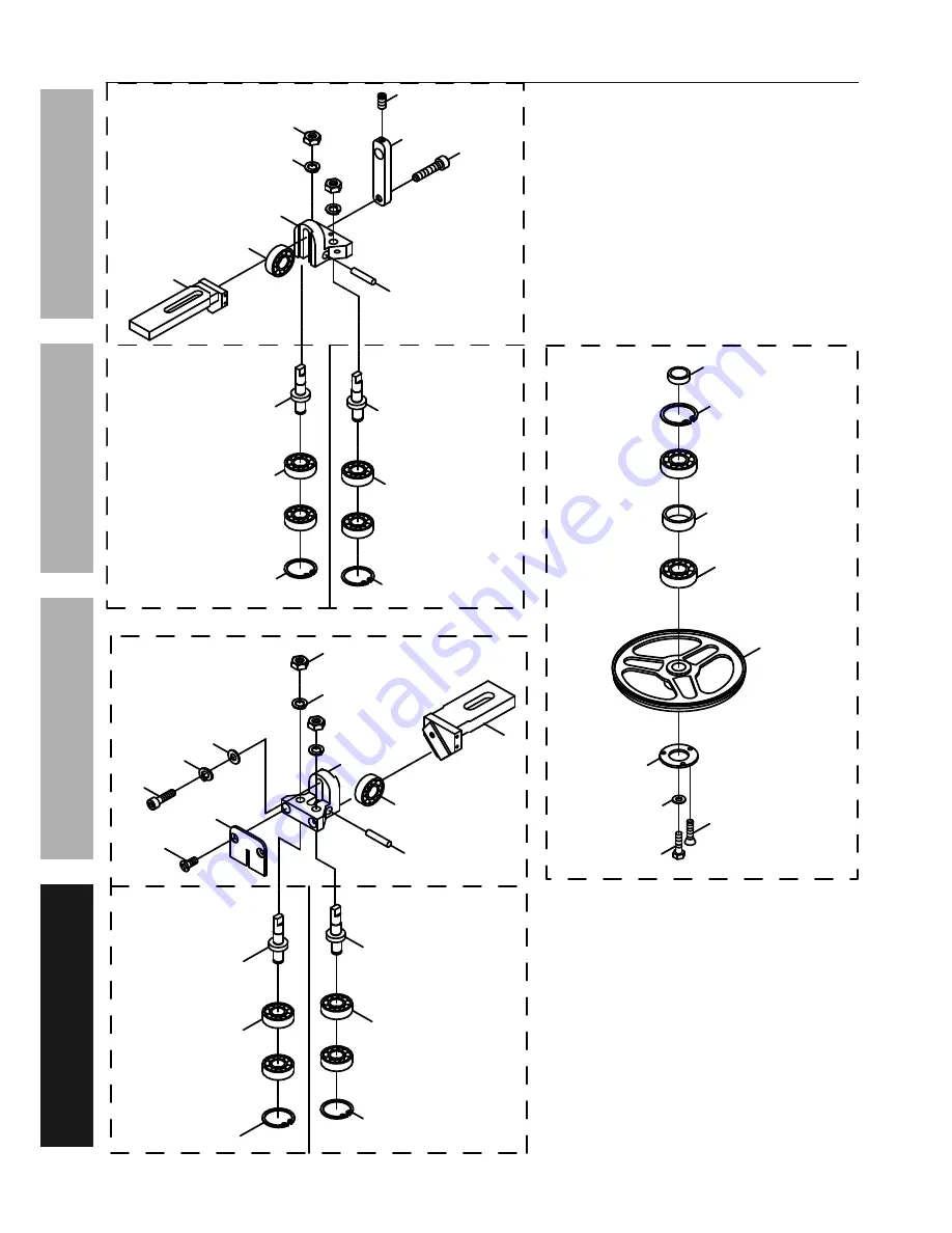
Assembly Diagrams - continued

268-2(2)

268S

267-3

268-3

267S

250-3

271-1

250-8

250-9

250-6

267-2(2)

268-1

267-1

266-6

266-3

266-7(2)

266-10

266-11

266-2

266-5

266-4

266-1

250S

250-7(3)

271S

266S

266-8(2)

266-9(2)

271-3

270-3

270S

270-2(2)

271-2(2)

270-1

250-4(2)

250-1

250-5

269-7

269S

269-1

269-3

269-4

269-2

269-6(2)

269-5(2)

269-9

269-8

250-2

Summary of Contents for 63469

Page 1: ...ence 18a When unpacking make sure that the product is intact and undamaged If any parts are missing or broken please call 1 888 866 5797 as soon as possible Copyright 2016 by Harbor Freight Tools All...

Page 2: ...ymbol It is used to alert you to potential personal injury hazards Obey all safety messages that follow this symbol to avoid possible injury or death Indicates a hazardous situation which if not avoid...

Page 3: ...th and nameplate ampere rating If in doubt use the next heavier gauge The smaller the gauge number the heavier the cord 10 WEAR PROPER APPAREL Do not wear loose clothing gloves neckties rings bracelet...

Page 4: ...pole receptacles that accept the tool s plug 6 Repair or replace damaged or worn cord immediately Grounding pin 125 VAc 3 prong plug and Outlet for up to 125 VAc and up to 15 A 7 This tool is intende...

Page 5: ...nd Saw and allow the Saw Blade to completely stop if the Saw Blade is to be backed out of an uncompleted cut 17 Use indoors only 18 If the teeth of the Saw Blade are so far apart that they straddle th...

Page 6: ...o vibration such as tingling numbness and white or blue fingers seek medical advice as soon as possible 2 Do not smoke during use Nicotine reduces the blood supply to the hands and fingers increasing...

Page 7: ...e floor surface See Figure A Figure A 3 Once the Bandsaw is lifted insert the Wheel Rod 92 4 through the two holes located at the bottom right side of the Stand 77S Slide one Wheel 92 2 on each end of...

Page 8: ...call 1 888 866 5797 Item 63469 SAFETy OpERATION MAINTENANcE SETUp Functions BLADE TENSIONER SAW BLADE pOWER SWITcH VISE HAND WHEEL cOOLANT pUMp SWITcH MOVEABLE VISE pLATE FEED cyLINDER cONTROLS ADJUS...

Page 9: ...Lock off to lock the Saw Head in place See Figure C 2 Open the Blade Back Cover 286S 3 Release Saw Blade tension by turning the Blade Tension Knob 245 4 Slip the old Saw Blade off the Idler Wheel 250...

Page 10: ...Blade Guide Bearings For example if a Saw Blade becomes dull on one side sooner than the other it will begin cutting crooked Replacing the Saw Blade will correct this problem but adjusting the Blade...

Page 11: ...Speed Before use change the Saw Blade 251 speed to suit the material being cut The chart below shows settings for several materials Material Motor pulley Saw pulley Speed Stainless Alloy Steel Bearing...

Page 12: ...e Stand of the Bandsaw Then re insert the Hose through the top of the Coolant Tank IMpORTANT Replace the water soluble coolant as often as is necessary to keep metal debris in the coolant from cloggin...

Page 13: ...Turn the Feed Knob on the Cylinder clockwise to decrease the feed rate 2 Turn the Feed Knob on the Cylinder counterclockwise to increase the feed rate NOTIcE Do not turn the Feed Knob more than one t...

Page 14: ...the Front Vise Jaw to the desired position Then tighten the Front Vise Jaw against the workpiece by turning the Hand Wheel clockwise FRONT VISE JAW REAR VISE JAW HAND WHEEL HAND WHEEL Figure M 4 Setti...

Page 15: ...38 that holds the Stop Block 41 to the Stock Stop Rod 40 See Figure Q 2 Adjust the Stop Block to the desired length position Then re tighten the Thumb Screw THUMB ScREW STOcK STOp ROD STOp BLOcK WORKp...

Page 16: ...how the Bandsaw is wired 4 Open the Coolant Valve then turn the Coolant Pump Switch on 5 Turn the Motor Switch on 6 Set the workpiece on the Vertical Table making sure to keep downward pressure on the...

Page 17: ...otor Switch on 8 Turn the Cylinder s Feed Lock on and slowly lower the Saw Head until the Saw Blade is just above the workpiece cut line 9 Allow the Saw Blade to turn up to full speed before feeding t...

Page 18: ...en parts damaged electrical wiring and any other condition that may affect its safe operation 2 Periodically wear ANSI approved safety goggles and NIOSH approved breathing protection and blow dust out...

Page 19: ...using 140 weight gear oil not included The new oil should just come to the edge of the Gearbox 202 1 Do not overfill 4 Remove the Gearbox Gasket Gearbox Cover and four Hex Socket Head Screws See Figur...

Page 20: ...oarse or too fine for workpiece 8 Gear not aligned properly 9 Gears need lubrication 1 Allow machine to work at its own rate 2 Replace Saw Blade See page 9 3 Wear ANSI approved safety goggles and NIOS...

Page 21: ...ee page 10 Blade cuts rough 1 Saw Blade turns too quickly 2 Feed pressure is too heavy 3 Saw Blade teeth are spaced too widely for the workpiece material 1 See page 11 for recommended speeds 2 Reduce...

Page 22: ...x1 L Hex Head Screw 7 73 5 16 x1 1 4 L Hex Head Screw 1 part Description Qty 75 3 16 x3 8 L Cross Round Head Screw 2 77S Stand Assembly 1 78 1 2 Hose 1 82 Coolant Tank 1 84S Pump 1 85 1 4 x5 8 L Cross...

Page 23: ...oss Socket Hex Head Screw 1 290 Plum handle 1 291 Motor Pulley Cover 1 293 1 4 x5 8 L Cross Socket Hex Head Screw 2 294 1 4 x19xt1 5 Washer 2 295 5x5x30L Key 1 296 Motor Pulley 1 297 1 4 x3 8 L Hex So...

Page 24: ...SAFETy OpERATION MAINTENANcE SETUp Assembly Diagrams E E 86 2 84S 82 93 2 98 1 56 98 2 4 98 4 4 98 3 8 73 69 69 68 88 78 85 2 90 5S 75 2 89 2 91S 3 42 48 2 45 47 2 4 49 2 30 1 13 42 1 46 14 2 15 2 92...

Page 25: ...1 245 246 254 253 252 220 4 219 4 242 4 239 237 2 244 218 238 307 243 4 307 2 2 307 1 2 240 2 241 2 215 2 213 3 232 214 3 217 233 210 211 212 234 2 259 2 258S 236 235 2 268S 267S 266S 256 20 209 136 2...

Page 26: ...ams continued 268 2 2 268S 267 3 268 3 267S 250 3 271 1 250 8 250 9 250 6 267 2 2 268 1 267 1 266 6 266 3 266 7 2 266 10 266 11 266 2 266 5 266 4 266 1 250S 250 7 3 271S 266S 266 8 2 266 9 2 271 3 270...

Page 27: ...ase call 1 888 866 5797 Item 63469 SAFETy OpERATION MAINTENANcE SETUp Assembly Diagrams continued 201S 202S 201 15 202 1 201 14 202 3 2 202 2 201 7 201 10 4 202 4 201 13 3 201 12 201 1 201 2 201 4 201...

Page 28: ...all 1 888 866 5797 Item 63469 SAFETy OpERATION MAINTENANcE SETUp Assembly Diagrams continued 751 2 751 4 751 3 2 751 5 751 9 751 7 2 751 6 751 751 1 751 9 751 8 2 750 3 750 6 750 5 750 11 750 8 2 750...

Page 29: ...al Schematic MOTOR Black Black Black White White Green Green Red Red 13A Overload 240VAc Electrical Schematic MOTOR Grey Black Black White White Green Green Red Red 7A Overload Black WARNING To preven...

Page 30: ...For technical questions please call 1 888 866 5797 Item 63469 SAFETy OpERATION MAINTENANcE SETUp Frequency Electrical Schematic Hz Wire color A B c D 50 Blue Black Brown Yellow Green 60 White Red Blac...

Page 31: ...Page 31 For technical questions please call 1 888 866 5797 Item 63469 SAFETy OpERATION MAINTENANcE SETUp 1 phase Electrical Schematic 3 phase Electrical Schematic...

Page 32: ...o the above limitation of exclusion may not apply to you THIS WARRANTY IS EXPRESSLY IN LIEU OF ALL OTHER WARRANTIES EXPRESS OR IMPLIED INCLUDING THE WARRANTIES OF MERCHANTABILITY AND FITNESS To take a...

Reviews: