background image

Page 6 SKU # 42827

UNPACKING AND INSTALLATION

1.

Remove protective crating and skids carefully. In the event of damage in transit, contact Harbor Freight
Tools immediately.

2.

Read the owner’s manual and become familiar with the parts and controls on the drawings before
using this machine, as familiarity with the controls will enhance your ability and safety in using it.

INSTALLATION

1.

It is important that the machine be located on a hard, solid, level floor. Find a location that
supplies easy access to 110 Volt electrical service. Make sure this machine is located in a well
lighted and well ventilated area. The floor should be resistant to vibration.

2.

Before moving the machine, be sure the head is fixed on the column. Before moving the machine, lower
the head as much as possible to lower the center of gravity. When moving the machine be careful to
keep it balanced, and not allow it to topple over.

3.

To set the machine on a solid concrete foundation, it’s advisable to apply a little grout to touch up
any uneveness in the concrete in order to get a solid foundation at all points.

4.

When setting machine on a floor that has any surface irregularities, shims should be used to
correct this condition to the greatest extent possible.

5.

There are 4 holes in the base for mounting the machine permanently to a smooth, solid, and level floor.

CLEANING AND LUBRICATION

1.

Thoroughly clean the machine with a commercial degreaser.
Do not use gasoline, kerosene or other flammable liquids.
Avoid getting  solvent on rubber parts, or into the electrical
controls or motor.

2.

After cleaning, coat all bright metal with a light lubricant to
prevent corrosion.

3.

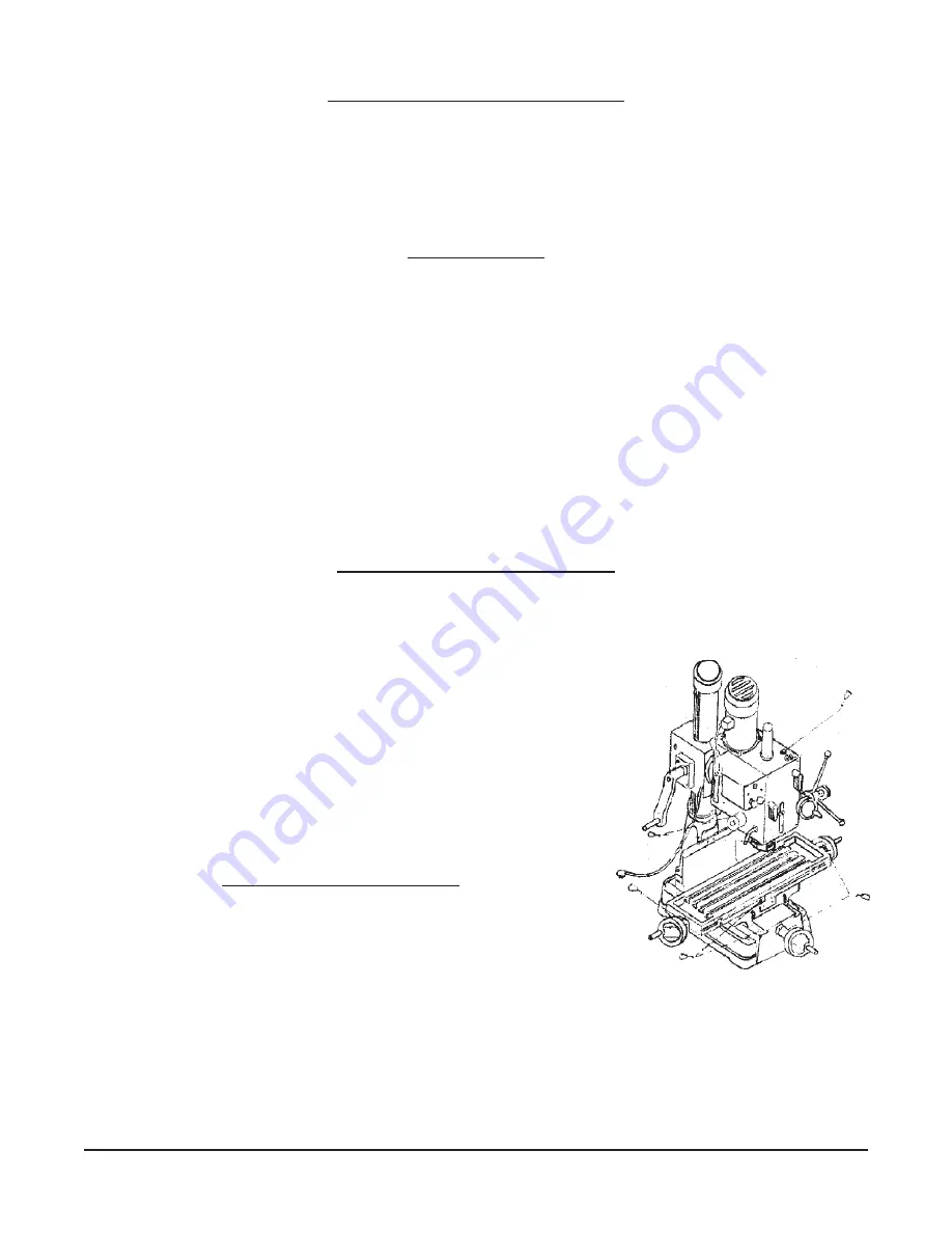
Lubricate all points indicated in 

Figure 2 

with a 10 weight

machine oil.

4.

Remove the oil filler plug and fill the reservoir with heavy motor
oil, until the oil level reaches the middle of the oil fluid level
indicator. Replace the plug.

LEVELING THIS MACHINE

1.

Before operation, it is critical to level the work surface both
lengthwise and crosswise, using a precision level. It will not be
possible to maintain accuracy of machined parts if the mill is not
properly leveled to start.

Figure 2. Lubrication Points.

Summary of Contents for 42827

Page 1: ...ww harborfreight com Copyright 2005 by Harbor Freight Tools All rights reserved No portion of this manual or any artwork contained herein may be reproduced in any shape or form without the express written consent of Harbor Freight Tools For technical questions and replacement parts please call 1 800 444 3353 TO PREVENT SERIOUS INJURY READ AND UNDERSTAND ALL WARNINGS AND INSTRUCTIONS BEFORE USE ...

Page 2: ...anged 9 Thread tapping operations can be done in either rotation and working depth can be controlled using a positivestopgauge Page 2 SKU 42827 SAVE THIS MANUAL Youwillneedthemanualforthesafetywarningsandcautions assemblyinstructions operatingprocedures maintenanceprocedures troubleshooting partslist anddiagram Keepyourinvoicewiththismanual Write the invoice number on the inside of the front cover...

Page 3: ...priate workclothing 8 USE EYE EAR AND BREATHING PROTECTION Always wear ANSI approved impact safety goggles if you are producing metal filings or wood chips Wear an ANSI approved dust mask or respirator when working around metal wood and chemical dusts and mists Use ANSI approved ear protection when working in a loud or noisy environment 9 DO NOT ABUSE THE POWER CORD Protect the power cord from dam...

Page 4: ...fied technician SPECIAL WARNINGS WHEN USING THIS DRILLING MILLING MACHINE Using this machine may create special hazards Take particular care to safeguard yourself and those around you Electrical Safety Never operate any tool if there is an electrical hazard Never operate an electrical tool in wet conditions Never operate a tool with an improper electrical cord or extension cord Never operate an el...

Page 5: ...6 OilDrainPlug 7 Table FeedWheel 8 TravelStop 9 Knob 10 RedBushButton 11 GreenPushButton 12 Leaf Screw 13 Cross Table Feed Wheel 14 Positive Depth Stop Gauge 15 Spindle Micro Feed Handle 16 Spindle Feed Handle 17 Speed Lever 18 AirFlowPlug 19 OilFillerPlug 20 Head Body 21 Arbor Bolt Cover 22 Scale Page 5 SKU 42827 Figure 1 ...

Page 6: ...t s advisable to apply a little grout to touch up any uneveness in the concrete in order to get a solid foundation at all points 4 Whensettingmachineonafloorthathasanysurfaceirregularities shimsshouldbeusedto correct this condition to the greatest extent possible 5 There are 4 holes in the base for mounting the machine permanently to a smooth solid and level floor CLEANINGAND LUBRICATION 1 Thoroug...

Page 7: ...dicallycheckthetightnessof thesenuts especiallyduringprolongeduseofthe machine 3 You may set the head at an angle by loosening the three nuts shown in the right part of Figure 3 Retighten the nuts when you have set the angle at the desired degree Refer to the scale on the right side of the head to read the angle Preparing for Drilling Please see Figure 4 1 Rotate the knob in the center of the spin...

Page 8: ...dragisfeltwhen movingthetable Locking the Table Base and Machine Base 1 Whenmillingusingthelongitudinalfeed itisagoodideato lock the cross feed table to ensure the accuracy of your work To do this tighten the small leaf screw located on the right side of the table base 2 Whenmillingusingthecrossfeed lockthelongitudinaltravel Dothisbytighteningthetwosmallleafscrewsonthefrontof the table base 3 Adju...

Page 9: ...detach the arbor bolt with the other hand 5 Replace the arbor bolt cover Installing a Face Mill or Cutter Arbor 1 Remove the arbor bolt cover 21 on the top of the head body 20 2 Insert the cutter and cutter abor into the taper of the spindle 3 Tighten the arbor bolt securely but do not overtighten 4 Replace the arbor bolt cover Additional Tools and Accessories You Will Find Helpful Your Drill Mill...

Page 10: ...ngaged The motor overheats or there is insufficient power 1 The machine is overloaded Reduce the feed rate and or increase the spindle speed 2 Thevoltagesupplyistoolow Ifyouhaveanunreliablepowersupply checkwithaqualifiedelectrician to repair it 3 The magnetic switch may have a burned or broken contact point Replace the switch 4 The contactor relay may be broken Replace it 5 The motor carbon brushe...

Page 11: ...echuckisloose Tightenthechuck 5 The drill bit or cutter is dull Sharpen or replace it Be sure to use cutting fluid to preserve tool life 6 The workpiece is not held firmly Check the clamps or vise you are using and assure that the workpiece cannotmove The micro feed does not work smoothly 1 The clutch may be loose Check this and tighten if necessary 2 The worm or worm shaft may be worn Check these...

Page 12: ...s designed to operate on 110 Volt 60 Hz Single Phase power supply only This machine is supplied with a 3 prong grounded plug Use only a power supply which is grounded and which is protected by an appropriate circuit breaker Check with a qualified electrician before using this machine Serious injury or damage to property can result from improper electrical connection WIRING DIAGRAM WIRING DIAGRAM K...

Page 13: ...inted metal to prevent corrosion 6 Cover the machine to prevent dust or dirt contamination when not in use Daily Maintenance 1 Fill the oil reservoir to the proper level before each use 2 Check the tightness of the bolts holding the head in place 3 If overheating is observed or unusual noises are produced stop the machine immediately to check for lackoflubrication faultyadjustments dulltoolbits or...

Page 14: ...34 Gear 1 1 35 BearingSpacer 1 1 36 Sleeve 1 1 37 Gear 1 1 38 Key 1 1 39 HandleRod 1 1 40 Knob 3 1 41 BallBearing 80202 3 1 42 InnerRing 1 P N Description Quantity P N Description Quantity 1 43 Shaft 1 1 44 MicroAdjustingIndicator 1 1 45 Worm Cover 1 1 46 BallBearing 202G 2 1 47 WormShaft 1 1 48 Key 2 1 49 Gear 1 1 50 OilSeal 1 1 51 BallBearing 80107 1 1 52 Head Body Fix Bolt 2 1 53 OilDrainPlug 1...

Page 15: ... 1 157 Retainer 1 1 158 Knob 1 1 184 Screw 1 1 185 Washer 1 1 187 Washer 1 1 188 Phillips Head Recessed Screw 1 1 189 TravelSwitchBaseA 1 1 190 TravelSwitchBaseB 1 P N Description Quantity 2 01 TableHandlewithWheel 3 2 02 DialClutch 2 2 03 ThrustBearing 8103 4 2 04 SquareFlange 1 2 05 Table Screw 1 2 06 Base 1 2 07 GibStrip 1 2 08 ColumnBase 1 2 09 ColumnBaseRing 1 2 10 Rack 1 2 11 ColumnHead 1 2 ...

Page 16: ...Page 16 SKU 42827 VERTICALMILLINGMACHINE HEAD PARTS DIAGRAM Please refer to Parts List on Pages 14 and 15 NOTE When ordering parts from this diagram use prefix 1 example P N 1 01 Arbor Bolt Cover ...

Page 17: ...Page 17 SKU 42827 VERTICALMILLINGMACHINE BASE PARTS DIAGRAM Please refer to Parts List on Page 15 NOTE When ordering parts from this diagram use prefix 2 example P N 2 01 Table Handle with Wheel ...

Reviews: