background image

SKU 04223

PAGE 8

3.

Use 

four

 Carriage Bolts (part #136), four Washers (part #138), and four Nuts

(part #139) to connect one Lower Side Brace (part #134) to the middle portion of
two Legs (part #133).  


Repeat this Step for the remaining one Lower Side Brace

and two Legs.  

(See Figure B.)

4.

Use 

six

 Carriage Bolts (part #136), six Washers (part #138), and six Nuts

(part #139) to connect one Upper Front/Back Brace (part #132) to the upper
portion of two Legs (part #133).  


Repeat this Step for the remaining one Upper

Front/Back Brace and two Legs.  

(See Figure B.)

5.

Use 

four

 Carriage Bolts (part #136), four Washers (part #138), and four Nuts

(part #139) to connect one Lower Front/Back Brace (part #135) to the middle
portion of two Legs (part #133).  


Repeat this Step for the remaining one Lower

Front/Back Brace and two Legs.  

(See Figure B.)

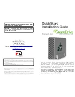
To Attach The Bench Top Planer To The Stand:

1.

With assistance, place the Bench Top Planer on top of the Stand, and align it’s
four mounting holes in it’s Base (part #111) with the four mounting holes in the
top of the Stand.  

(See Figure C.)

2.

Use 

four

 Hex Bolts (part #137), four Washers (part #138), and four Nuts

(part #139) to firmly secure the Bench Top Planer to the Stand.  

(See Figure C.)

STAND

ASSEMBLY

WASHER (#138)

NUT (#139)

HEX BOLT (#137)

BENCH TOP PLANER

FIGURE C

Summary of Contents for 04223

Page 1: ...11 Visit our Web site at http www harborfreight com Copyright 2003 by Harbor Freight Tools All rights reserved No portion of this manual or any artwork contained herein may be reproduced in any shape...

Page 2: ...RK AREA CLEAN AND DRY Cluttered damp or wet work areas invite injuries 2 KEEP CHILDREN AWAY FROM WORK AREA Do not allow children to handle this product 3 STORE IDLE EQUIPMENT When not in use tools and...

Page 3: ...nded for use with this product Approved accessories are available from Harbor Freight Tools 12 MAINTAIN THIS PRODUCT WITH CARE Keep this product clean dry and keep the Cutting Blades part 22 sharp for...

Page 4: ...P PLANER IS FACTORY PRE WIRED FOR 120 VOLT AC USAGE The electrical Power Cord part 22A for this product is equipped with a grounded 120 Volt AC Plug Never modify the Plug in any way To com ply with th...

Page 5: ...ORE PLANING ANY WORKPIECE CHECK FOR ANY FOREIGN MATERI ALS SUCH AS NAILS SCREWS OR HARD IMPURITIES IN THE WOOD Also check for loose knots in the workpiece 16 AFTER EACH PLANING USE THE ROLLERS part 7...

Page 6: ...ea and work with approved safety equipment such as those dust masks that are specially designed to filter out microscopic particles California Health Safety Code 25249 5 et seq 24 WARNING People with...

Page 7: ...Use four 1 4 diameter Hex Bolts of appropriate length four Lockwashers and four Nuts all not included to firmly secure the Bench Top Planer to the work bench To Assemble The Stand For Use 1 NOTE All h...

Page 8: ...igure B 5 Use four Carriage Bolts part 136 four Washers part 138 and four Nuts part 139 to connect one Lower Front Back Brace part 135 to the middle portion of two Legs part 133 Repeat this Step for t...

Page 9: ...uler run from 0 to 6 See Figure D 3 After adjusting the planing depth make sure to lower the Head Lock Assembly part 52 to lock the desired adjustment in position To Preset The Depth Gauge 1 The plani...

Page 10: ...e two Magnets part 125 provided to remove the Gib part 23 from the Cutterhead part 20 See Figure E 6 Use the two Magnets part 125 to remove the Blade part 22 from the Cutterhead part 20 See Figure E 7...

Page 11: ...nd that the Power Cord part 22A is unplugged from its electrical power outlet See Figure D 2 Lift up on the Head Lock Lever Assembly part 52 Then turn the Handle Assembly part 11 clockwise to raise th...

Page 12: ...inst the Blades to stop them 10 When feeding the workpiece use a push block not included to feed the workpiece rather than using your hands The push block must be thinner than three inches 11 When pla...

Page 13: ...flat If possible rip the board down the middle of the cup This will eliminate a large amount of waste in the planing process See Figure G Grain Direction 1 Feeding the board into the Bench Top Planer...

Page 14: ...ng parts 4 AFTER PLANING APPROXIMATELY 50 FEET OF MATERIAL turn off the Bench Top Planer and unplug it from its electrical outlet Then check the Screws part 19 connecting the Gib part 23 and Blades pa...

Page 15: ...SKU 04223 PAGE 15 PARTS LIST 7 5 7 5 J J 5 7 5 5 J 5 J 6 J 7 8 5 6 J 7 7 J J 5 6 5 J 8 7 7 J 5 5 7 6 7 5 7 7 7 6 77 6 7 7 7 7 7 7...

Page 16: ...SKU 04223 PAGE 16 J 5 6 J 7 7 5 J 5 5 5 5 J 7 6 7 6 8 6 6 5 J 7 J J 7 J 6 7 5 J 77 J 7 7 J J 7 J 5 J 7 J J 7 J 7 J 888888888 8888888888888888888888888888888888 888888 7 J PARTS LIST CONTINUED...

Page 17: ...67 68 7071 69 127 72 38 21 73 74 75 79 80 81 47 86 112 87109 88 91 92 93 94 95 39 40 130 43 126 15 45 47 48 49 47 50 51 85 89 90 98 96 47 29 30 78 116 108 4 99 100 101 44 102 103 104 77 76 106 107 114...

Page 18: ...d are not available individually as replacement parts 13A 1A 2A 3A 4A 5A 6A 7A 8A 9A 10A 11A 12A 13AA 14A 15A 16A 17A 18A 19A 20A 21A NOTE ONLY PARTS 14A 15A AND 16A MAY BE ORDERED INDIVIDUALLY ALL OT...

Reviews: