background image


2

2.


General Information 

2.1


On-Board Diagnostics (OBD) II   

The first generation of On-Board Diagnostics (called OBD I) was 
developed by the California Air Resources Board (ARB) and 
implemented in 1988 to monitor some of the emission control 
components on vehicles. As technology evolved and the desire to 
improve the On-Board Diagnostic system increased, a new generation of 
On-Board Diagnostic system was developed. This second generation of 
On-Board Diagnostic regulations is called "OBD II".   

The OBD II system is designed to monitor emission control systems 
and key engine components by performing either continuous or 
periodic tests of specific components and vehicle conditions. When a 
problem is detected, the OBD II system turns on a warning lamp (MIL) 
on the vehicle instrument panel to alert the driver typically by the 
phrase of “Check Engine” or “Service Engine Soon”. The system will 
also store important information about the detected malfunction so that 
a technician can accurately find and fix the problem. Here below 
follow three pieces of such valuable information:   

1)


Whether the Malfunction Indicator Light (MIL) is 
commanded 'on' or 'off'; 

2)


Which, if any, Diagnostic Trouble Codes (DTCs) are stored;   

3)


Readiness Monitor status. 

2.2


Diagnostic Trouble Codes (DTCs) 

OBD II Diagnostic Trouble Codes are codes that are stored by the 
on-board computer diagnostic system in response to a problem found 
in the vehicle. These codes identify a particular problem area and are 
intended to provide you with a guide as to where a fault might be 
occurring within a vehicle. OBD II Diagnostic Trouble Codes consist 
of a five-digit alphanumeric code. The first character, a letter, 
identifies which control system sets the code. The other four characters, 
all numbers, provide additional information on where the DTC 
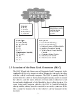
originated and the operating conditions that caused it to set. Here 
below is an example to illustrate the structure of the digits: 

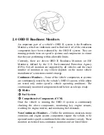
Summary of Contents for 99722

Page 1: ......

Page 2: ...scription 8 3 2 Specifications 10 3 3 Accessories Included 10 3 4 Navigation Characters 10 3 5 Keyboard 11 3 6 Power 11 3 7 Code Lookup 11 3 8 Product Setup 13 3 9 Tool Information 20 3 10 Battery Replacement 21 3 11 Vehicle Coverage 21 3 12 Product Troubleshooting 22 4 Review Data 23 5 OBD II Diagnostics 24 5 1 Reading Codes 26 5 2 Erasing Codes 28 5 3 Viewing Freeze Frame Data 30 5 4 Retrieving ...

Page 3: ...n front of the drive wheels and never leave the vehicle unattended while running tests z Use extreme caution when working around the ignition coil distributor cap ignition wires and spark plugs These components create hazardous voltages when the engine is running z Put the transmission in PARK for automatic transmission or NEUTRAL for manual transmission and make sure the parking brake is engaged ...

Page 4: ...e Soon The system will also store important information about the detected malfunction so that a technician can accurately find and fix the problem Here below follow three pieces of such valuable information 1 Whether the Malfunction Indicator Light MIL is commanded on or off 2 Which if any Diagnostic Trouble Codes DTCs are stored 3 Readiness Monitor status 2 2 Diagnostic Trouble Codes DTCs OBD II...

Page 5: ...uropean vehicles the DLC is located behind the ashtray and the ashtray must be removed to access the connector If the DLC cannot be found refer to the vehicle s service manual for the location Identifying specific malfunctioning section of the systems Systems B Body C Chassis P Powertrain U Network DTC Example P 0 2 0 2 Sub systems 1 Fuel and Air Metering 2 Fuel and Air Metering 3 Ignition System ...

Page 6: ...manufacturer s emissions control strategy Continuous Monitors Some of the vehicle components or systems are continuously tested by the vehicle s OBD II system while others are tested only under specific vehicle operating conditions The continuously monitored components listed below are always ready 1 Misfire 2 Fuel System 3 Comprehensive Components CCM Once the vehicle is running the OBD II system...

Page 7: ...ess codes to Ready varies for each individual monitor Once a monitor is set as Ready or Complete it will remain in this state A number of factors including erasing of diagnostic trouble codes DTCs with a scan tool or a disconnected battery can result in Readiness Monitors being set to Not Ready Since the three continuous monitors are constantly evaluating they will be reported as Ready all of the ...

Page 8: ...entify which section of the emission control system has malfunctioned Enabling Criteria Also termed Enabling Conditions They are the vehicle specific events or conditions that must occur within the engine before the various monitors will set or run Some monitors require the vehicle to follow a prescribed drive cycle routine as part of the enabling criteria Drive cycles vary among vehicles and for ...

Page 9: ... of the vehicle operating parameters to help in identifying the problem This set of values is referred to as Freeze Frame Data and may include important engine parameters such as engine RPM vehicle speed air flow engine load fuel pressure fuel trim value engine coolant temperature ignition timing advance or closed loop status ...

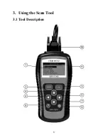
Page 10: ...3 Using the Scan Tool 3 1 Tool Description 8 ...

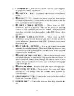
Page 11: ...iews additional information when DTC definition covers more than one screen UP SCROLL BUTTON Moves up through menu and submenu items in menu mode When more than one screen of data is retrieved moves up through the current screen to the previous screens for additional data DOWN SCROLL BUTTON Moves down through menu and submenu items in menu mode When more than one screen of data is retrieved moves ...

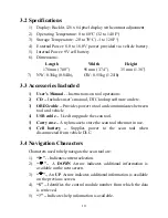
Page 12: ...TC lookup software and etc 3 OBD2 cable Provides power to tool and communicates between tool and vehicle 4 USB cable Used to upgrade the scan tool 5 Carry case A nylon case to store the scan tool when not in use 6 Cell battery Supplies power to the scan tool when disconnected from vehicle DLC 3 4 Navigation Characters Characters used to help navigate the scan tool are 1 Indicates current selection...

Page 13: ...If the scan tool is stored for a long period of time remove batteries to prevent battery leakage from damaging battery compartment External Power External power of the scan tool is provided via the vehicle Data Link Connector DLC Just follow the steps below to turn on the scan tool 1 Connect the OBD II Cable to scan tool 2 Find DLC on vehicle A plastic DLC cover may be found for some vehicles and ...

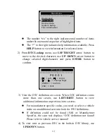
Page 14: ...ted digit character and press ENTER button to confirm DTC Lookup P 0 0 0 1 Left Right Change Digit ENTER Confirm ESC Exit 3 View the DTC definition on screen When DTC definition covers more than one screen use LEFT RIHT button to view additional information on previous next screens z For manufacturer specific codes you need to select a vehicle make on an additional screen to look for DTC definitio...

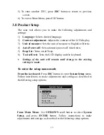
Page 15: ... Set Turns on off beep 6 Tool self test Tests the LCD display and the keyboard Settings of the unit will remain until change to the existing settings is made To enter the setup menu mode From the keyboard Press ESC button to enter System Setup menu Follow instructions to make adjustments and settings as described in the following setup options System Setup 1 6 Language Contrast Unit of Measure Aut...

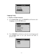
Page 16: ...em Setup menu use UP DOWN scroll button to select Language and press ENTER button System Setup 1 6 Language Contrast Unit of Measure Auto Power off Beep Set Tool Self test 2 Use UP DOWN scroll button to select the desired language and press ENTER button to save your selection and return to previous menu Language 1 3 English Français Español ...

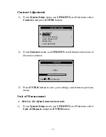
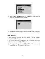
Page 17: ...ase or decrease contrast 3 Press ENTER button to save your settings and return to previous menu Unit of Measurement Metric is the default measurement unit 1 From System Setup menu use UP DOWN scroll button to select Unit of Measure and press ENTER button Contrast 30 System Setup 2 6 Language Contrast Unit of Measure Auto Power off Beep Set Tool Self test Use or to change ...

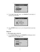
Page 18: ...mum automatic power off time is 1 minute and the maximum is 20 minutes Automatic power off setup function can be available only when the scanner is powered by cell battery 1 From System Setup menu use UP DOWN scroll button to select Auto Power off and press ENTER button Unit of Measure 2 2 System Setup 3 6 Language Contrast Unit of Measure Auto Power off Beep Set Tool Self test English Metric ...

Page 19: ...e default setting is Beep On 1 From System Setup menu use UP DOWN scroll button to select Beep Set and press ENTER button Auto Power off System Setup 4 6 Language Contrast Unit of Measure Auto Power off Beep Set Tool Self test 01 Minute Increase time Decrease time ENTER Confirm System Setup 5 6 Language Contrast Unit of Measure Auto Power off Beep Set Tool Self test ...

Page 20: ... Tool Self test function checks if the display and keyboard are working properly A Display test The Display Test function checks if the LCD display is working normally 1 From System Setup menu use UP DOWN scroll button to select Tool Self Test and press ENTER button System Setup 6 6 Language Contrast Unit of Measure Auto Power off Beep Set Tool Self test 2 Select Display Test from Tool Self Test m...

Page 21: ...ard Test The Keyboard Test function verifies if the keys are working properly 1 Use UP DOWN scroll button to select Keyboard Test from Tool Self test menu and then press ENTER button Tool Self test 2 2 Display Test Keyboard Test 2 Press any key to start test When you press a key the key name should be observed on the display If the key name does not show up then the key is not working properly ...

Page 22: ... the scanner or power off the scanner the key is not working properly 3 Double press ESC to return to previous menu 3 9 Tool Information The Tool Information function allows viewing of some important information such as serial number and software version number of the scan tool 1 From Main Menu use UP DOWN scroll button to select Tool Information and press ENTER button Main Menu 5 5 Diagnostics DT...

Page 23: ...signed to work with all OBD II compliant vehicles including those equipped with next generation protocol Control Area Network CAN It is required by EPA that all 1996 and newer vehicles cars and light trucks sold in the United States must be OBD II compliant and this includes all Domestic Asian and European vehicles A small number of 1994 and 1995 model year gasoline vehicles are OBD II compliant T...

Page 24: ...ait for about 10 seconds Turn the ignition back to on and continue the testing 9 Verify the control module is not defective Operating Error If the scan tool freezes then an exception occurs or the vehicle s ECU Engine Control Unit is too slow to respond to requests You need to do the following to reset the tool 9 Press and hold POWER button for at least 2 seconds to reset the scan tool 9 Turn the ...

Page 25: ...Menu and press ENTER button Main Menu 3 5 Diagnostics DTC Lookup Review Data System Setup Tool Information 23 2 Use UP DOWN scroll button to select the desired item from Review Data menu and press ENTER button Review Data 1 5 Stored Codes Pending Codes Freeze Frame I M Readiness Vehicle Info z If there is no data stored for selected item a Not Supported or Stored No Data message shows on the scree...

Page 26: ...test equipment with ignition on or engine running 1 Turn the ignition off 2 Locate the vehicle s 16 pin Data Link Connector DLC 3 Plug into the scan tool cable connector to the vehicle s DLC 4 Turn the ignition on Engine can be off or running 5 Press ENTER button to enter Main Menu Use UP DOWN scroll button to select Diagnostics from the menu Main Menu 1 5 Diagnostics DTC Lookup Review Data System...

Page 27: ... tool to communicate with the vehicle Contact your local distributor or the manufacturer s customer service department for assistance 7 You will be prompted to erase previously stored data z Review previously stored data thoroughly before erasing Diagnostic Erase previously stored data to save data from this test YES NO z If no data is stored in the scan tool above prompt will not show up 8 If you...

Page 28: ...e the malfunction indicator lamp MIL when emission related fault occurs Pending Codes are also referred to as maturing codes or continuous monitor codes They indicate problems that the control module has detected during the current or last driving cycle but are not considered serious yet Pending Codes will not turn on the malfunction indicator lamp MIL If the fault does not occur within a certain ...

Page 29: ...to select Stored Codes or Pending Codes from the Trouble Codes menu and press ENTER button Trouble Codes 1 2 Stored Codes Pending Codes z If there are no Diagnostic Trouble Codes present the display indicates No pending codes are stored in the module Wait a few seconds or press any key to return to Diagnostic Menu 3 View DTCs and their definitions on screen 09 1 5 P0118 Generic Engine Coolant Temp...

Page 30: ... button to select manufacturer and then press ENTER button to confirm 28 Vehicle Manufacturer 1 51 Alfa Romeo Audi VW BMW Buick Cadillac Chevrolet z If the manufacturer for your vehicle is not listed use UP DOWN scroll button to select Other and press ENTER button 5 2 Erasing Codes CAUTION Erasing the Diagnostic Trouble Codes may allow the scan tool to delete not only the codes from the vehicle s ...

Page 31: ...ing for your confirmation Erase Codes Erase trouble codes Are you sure YES NO z If you do not want to proceed with erasing codes press ESC button or use LEFT RIGHT scroll button to select NO to exit A message of Command Cancelled show ups Wait a few seconds or press any key to return to Diagnostic Menu 3 Press ENTER button to confirm z If the codes are cleared successfully an Erase Done confirmati...

Page 32: ...ess any key to con P k t 4 Press any button to return to Diagnostic Menu 5 3 Viewing Freeze Frame Data 1 To view freeze frame data use UP DOWN scroll button to select View Freeze Frame from Diagnostic Menu and press ENTER button Diagnostic Menu 3 6 Read Codes Erase Codes View Freeze Frame I M Readiness Vehicle Info Unit of Measure 2 Wait a few seconds while the scan tool validates the PID MAP 30 ...

Page 33: ...ze Frame 2 DTC_CNT 1630 FUELSYS1 OL FUELSYS2 N A LOAD_PCT 0 0 ECT 40 SHRTFT1 0 0 z If there is no freeze frame data available an advisory message No freeze frame stored shows on the display 4 If you want to view full name of a PID use UP DOWN scroll button to select the PID and press HELP button FUELSYS1 Fuel System 1 Status Press any key to con 5 Wait a few seconds or press any button to return t...

Page 34: ...atus result of NO does not necessarily indicate that the vehicle being tested will fail the state I M inspection For some states one or more such monitors may be allowed to be Not Ready to pass the emissions inspection z OK Indicates that a particular monitor being checked has completed its diagnostic testing z INC Indicates that a particular monitor being checked has not completed its diagnostic ...

Page 35: ...e MIL light ON or OFF and the following monitors z Misfire monitor Misfire monitor z Fuel System Mon Fuel System Monitor z Comp Component Comprehensive Components Monitor z EGR EGR System Monitor z Oxygen Sens Mon O2 Sensors Monitor z Catalyst Mon Catalyst Monitor z EVAP System Mon Evaporative System Monitor z Oxygen Sens htr O2 Sensor Heater Monitor z Sec Air System Secondary Air Monitor z Htd Ca...

Page 36: ...itor OK Fuel System Mon N A Comp Component OK Catalyst Mon INC Htd Catalyst N A 6 Press ESC button to return to Diagnostic Menu 5 5 Viewing Vehicle Information The Vehicle Info function enables retrieval of Vehicle Identification No VIN Calibration ID No s Calibration Verification Nos CVNs and In use Performance Tracking on 2000 and newer vehicles that support Mode 9 1 Use UP DOWN scroll button to...

Page 37: ... on with engine off Press any key to con 3 Wait a few seconds while the scan tool reads vehicle information Vehicle Info Reading Info Please Wait z If the vehicle does not support this mode a message shows on the display warning that the mode is not supported 4 From Vehicle Info menu use UP DOWN scroll button to select an available items and press ENTER button ...

Page 38: ... Vehicle Info 2 3 Vehicle ID Number Calibration ID Cal Verif Number 36 5 View the vehicle information retrieved Calibration ID Cal ID1 LMC720 6 Press ESC button to return previous menu ...

Page 39: ...1 LONGFT3 Long Term Fuel Trim Bank3 SHRTFT2 Short Term Fuel Trim Bank2 SHRTFT4 Short Term Fuel Trim Bank4 LONGFT2 Long Term Fuel Trim Bank2 LONGFT4 Long Term Fuel Trim Bank4 FRP kPa Fuel Rail Pressure gauge FRP psi Fuel Rail Pressure gauge MAP kPa Intake Manifold Absolute Pressure MAP inHg Intake Manifold Absolute Pressure RPM min Engine RPM VSS km h Vehicle Speed Sensor VSS mph Vehicle Speed Sens...

Page 40: ...uel Trim B2S1 O2B2S2 V O2 Sensor Output Voltage B2S2 SHRTFTB2S2 Short Term Fuel Trim B2S2 O2B2S3 V O2 Sensor Output Voltage B2S3 SHRTFTB2S3 Short Term Fuel Trim B2S3 O2B2S4 V O2 Sensor Output Voltage B2S4 SHRTFTB2S4 Short Term Fuel Trim B2S4 O2B1S1 V O2 Sensor Output Voltage B2S1 SHRTFTB1S1 Short Term Fuel Trim B2S1 O2B1S2 V O2 Sensor Output Voltage B1S2 SHRTFTB1S2 Short Term Fuel Trim B1S2 O2B2S1...

Page 41: ... range O2S B1S1 O2B1S1 V O2 Sensor Voltage wide range O2S B1S1 EQ_RATB1S2 Equivalence Ratio wide range O2S B1S2 O2B1S2 V O2 Sensor Voltage wide range O2S B1S2 EQ_RATB1S3 Equivalence Ratio wide range O2S B1S3 O2B1S3 V O2 Sensor Voltage wide range O2S B1S3 EQ_RATB1S4 Equivalence Ratio wide range O2S B1S4 O2B1S4 V O2 Sensor Voltage wide range O2S B1S4 EQ_RATB2S1 Equivalence Ratio wide range O2S B2S1 ...

Page 42: ...O2S B3S2 EQ_RATB4S1 Equivalence Ratio wide range O2S B4S1 O2B4S1 V O2 Sensor Voltage wide range O2S B4S1 EQ_RATB4S2 Equivalence Ratio wide range O2S B4S2 O2B4S2 V O2 Sensor Voltage wide range O2S B4S2 EGR_PTC Commanded EGR EGR_ERR EGR Error EVAP_PCT Commanded Evaporative Purge FLI Fuel Level Input WARM_UPS Number of Warm ups Since DTC Cleared CLR_DIST km Distance Since DTC Cleared CLR_DIST mile Di...

Page 43: ...tio wide range O2S B2S1 O2S11 mA O2 Sensor Current wide range O2S B2S1 EQ_RAT12 Equivalence Ratio wide range O2S B1S2 O2S12 mA O2 Sensor Current wide range O2S B1S2 EQ_RAT21 Equivalence Ratio wide range O2S B2S1 O2S21 mA O2 Sensor Current wide range O2S B2S1 EQ_RAT22 Equivalence Ratio wide range O2S B2S2 O2S22 mA O2 Sensor Current wide range O2S B2S2 EQ_RAT31 Equivalence Ratio wide range O2S B3S1 ...

Page 44: ...VPWR V Control Module Voltage LOAD_ABS Absolute Load Value EQ_RAT Commanded Equivalence Ratio TP_R Relative Throttle Position AAT F Ambient Air Temperature AAT C Ambient Air Temperature TP_B Absolute Throttle Position B TP_C Absolute Throttle Position C APP_D Accelerator Pedal Position D APP_E Accelerator Pedal Position E APP_F Accelerator Pedal Position F TAC_PCT Commanded Throttle Actuator Contr...

Page 45: ......

Reviews: