

RTC1...
RTC2...
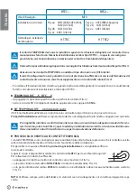
Fixing screw:
M10
For use with rails:
Fig. 2a: 49E1 (S49), 54E3 (S54),
54E2 (UIC54E)
Fig. 2b: 54E1 (UIC54)
Fig. 2c: 60E1 (UIC60)
Fig. 2a: 45E3 (RN45 Spain)
Fig. 2b: 54E1 (UIC54)
Fig. 2c: 60E1 (UIC60)
Installation/ removal
tool:
HT-TRC
HT-TRC2
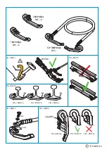
The TEMPORAIL connector must only be installed according to the detailed instructions in the operation
and maintenance manual provided with the Cembre HT-TRC ..installation tool; in order to ensure correct
installation and removal of the TEMPORAIL and the safety of the operator.
To prevent injuries to operators we recommend to avoid installation by means of impact tools (FIG.1).
Ensure the TEMPORAIL connector is suited to the type of rail in use (see table).
Correct connection is not guaranteed in the case of insuffi
cient pressure or excessive deformation of the
connector due to incorrect attachment to the lower part of the rail (FIG. 2).
- To install the connector, follow the detailed instructions in the use and maintenance manual provided with
the Cembre HT-TRC... installation tool.
TEMPORAIL RTC...-S RTC...-V
- Place the specifi c cable lug on the contact surface (FIG. 3)
- Secure with the M10 screw and washer, applying a torque ratio of
50 Nm
.
KIT TEMPORAIL RTC... (complete with cable)
The KIT is used to restore continuity of the rail and is equipped with a cable.
Before completing installation
, always check the cable and the correct tightening of the cable lugs.
It is recommended to install the connectors close to the sleepers, enough distance apart to make the
cable lie straight along the rail (FIG. 4); this prevents any possible damage to the connectors and to the
cable caused by tamping machines or other rail maintenance machines.
TEMPORAIL CONNECTOR TEST PROCEDURE
TEMPORAIL connector are designed to be reused many times; however, the pressure exerted by the clamp on
the rail tends to diminish gradually with the increasing number of installations.
To ensure maximum reliability, it is recommended to test the clamp
before every
installation
.
Use GO-NO GO gauge
CAL-RTC1
, to check the Y dimension.
To test the clamp:
- rest the clamp on the checking gauge as shown in FIG. 5 a.
- if the cylindrical part of the gauge
DOES NOT GO
, the connector can be reused, FIG. 5 b.
- if the cylindrical part of the gauge
GOES
, the connector cannot be used and must be discarded, FIG. 5 c.
NOTE:
Always check the cable and correct tightening of the cable lugs before completing the installation.
Y
ENGLISH


