6
2.6) Head opening
(Ref. to Fig. 4)
When required, the upper part of the head can be disconnected to permit an easy introduction of
the connector or, if necessary, the connector removal after crimping; operate as follows:
– Hold the handle (22), press the latch (9) and turn the top of the head through 90 degrees.
– Introduce the connector then replace the top of the head.
Before proceeding with the crimping operations, please
verify that the head is correctly reassem-
bled and latch (9) is correctly located.
3. MAINTENANCE
The head is robust and requires very little daily maintenance.
Inspect for wear and damage. Worn or damaged parts may malfunction during head operation.
The parts must be replaced if signs of wear or damage are evident.
Compliance with the following points should help to maintain the optimum performance of the tool.
3.1) Accurate cleaning
Dust, sand and dirt are a danger for any hydraulic device.
Avoid putting the head on muddy or dusty ground as dirt particles may score the ram and create
oil leaks.
Every day, after use, the head must be wiped with a clean cloth, taking care to remove any residue,
especially around moving parts.
3.2) Replacement of the automatic coupler
To replace the automatic coupler proceed as follows:
– Remove the old coupler.
– Carefully clean the thread to remove the old sealant.
– Apply Tefl on tape to the thread.
– Fit the new automatic coupler and tighten to
30 Nm
(22 lbf ft).
3.3) Storage
(Ref. to Fig. 2)
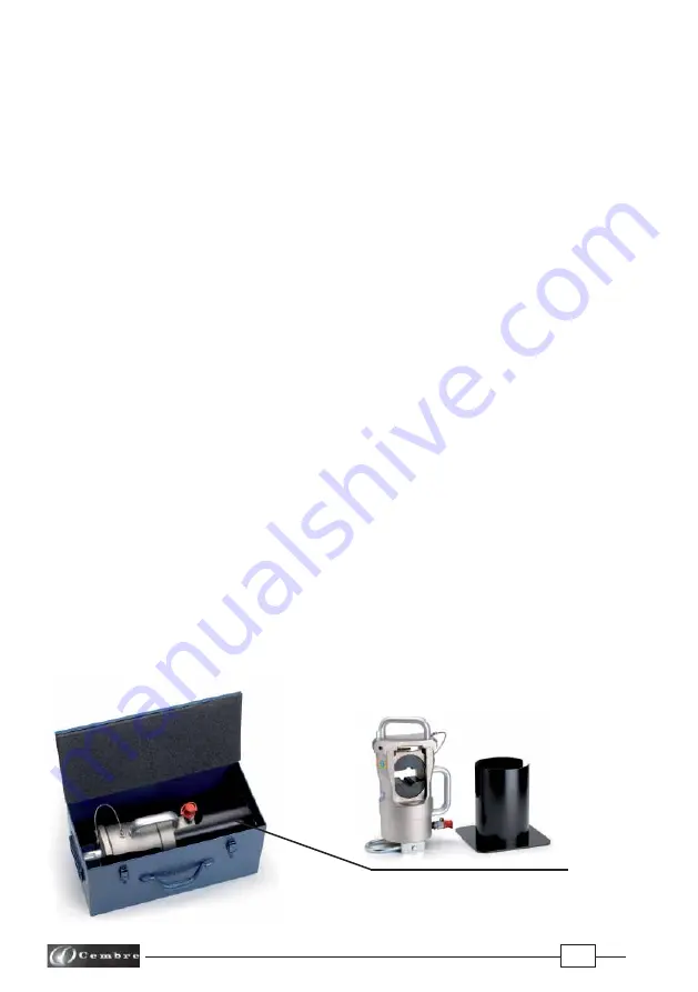
When not in use, the head should be stored and transported in the specifi c steel case to prevent
damage.
Steel case:
VAL600
, size 480x235x260 mm (18.9x9.2x10.2 in.) weight 8,6 kg (18.9 lbs) suitable for
storing the head complete with support.
FIG. 2
VAL600 METAL CASE


