


6
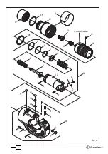
FIG. 4
Code N°
Item
DESCRIPTION
Qty
6620250
03 3 RELEASE PIN COVER
1
6620245
03 4 RELEASE PIN
1
6760160
03 5 SPRING PIN ø 3x28
1
6620440
03 6 RETAINING PIN
1
6522006
03 7 SPRING
1
6120127
04
CYLINDER
1
6170184
05
CYLINDER COVER
1
6120128
06
MOVEABLE RING NUT
1
6100035
07
KEY 1
6362035
08
SEAL *
1
6700065
09
CIRCLIP
1
6340060
10
GRUB SCREW M6x6
1
6170143
12
PLASTIC CAP
2
6232894
13
LABEL TG1118
1
6900210
14
SCREW M5x10
1
6060128
15
QUICK COUPLER I38-MS
1
Code N°
Item
DESCRIPTION
Qty
6650220
01
ADAPTER
1
6620312
02
COMPLETE RAM
1
6522006
02 1 SPRING
1
6760040
02 2 SPRING PIN
2
6040128
02 3 BACK-UP RING *
1
6362058
02 4 SEAL
*
1
6620445
02 5 RELEASE PIN
1
6620320
02 6 RETAINING PIN
1
6700250
02 7 CIRCLIP ø 36
1
6520611
02 8 INT. SPRING
1
6170140
02 9 SPRING COVER
1
6520619
02 10 EXT. SPRING
1
6300079
02 11 RAM GUIDE
1
-
02 12 RAM
1
6370238
03
COMPLETE “C” HEAD
1
6800088
03 1 PLASTIC CAP
1
6340540
03 2 GRUB SCREW M10x8
1
The items marked "
*
" are those
Cembre
recommend replacing if the tool is disassembled.
When ordering spare parts always specify the following:
- Code N° of item - description of item - tool type - tool serial number
6. PART LIST
(Ref. to FIG. 4)
Connector
Conductor
die set
FIG. 3