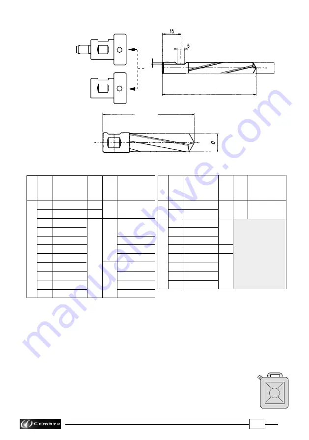
Cembre LD-41P Operation And Maintenance Manual Download Page 8

8

FIG. 1

FIG. 2

The drilling tools indicated in the table guarantee optimum results. For tools of other types, check the dimen-
sional compatibility (particularly the size of the attachment and the length).

3.10) LR2 BIODEGRADABLE LUBROCOOLANT

3 litre container to be used in a 5-10 % solution, for optimum operation of both broach cutters 
and 

spiral bits.

3.11)  LR3 ANTIFREEZE CONCENTRATE


3 litre added to the lubrocoolant mixture in the right concentration will
maintain the lubrocoolant mixture fluid in negative temperature conditions.

–  The special spiral bits in the 

PE


range allow automatic cooling by means of the 

SR5000


u

nit supplied with 

  the drilling machine.

–  All spiral bits in the


PE


range allow drilling of 

thicknesses up to 45 mm.

L max

ø

APED... 
 

           APE...

ø

L max

h

3.9)  Spiral bits

7

7,1

8

8,5

9

9,5

10
11
12
13

13,5

SPECIAL SPIRAL BITS FOR RAILS IN STEEL QUALITY 700 - 900 - 1100 (UIC 860.0)

PE 140
PE 160
PE 170AR
PE 175
PE 180
PE 190AR
PE 210AR
PE 220
PE 240AR
PE 275AR

Ø 

mm

14
16
17

17,5

18
19
21
22
24

27,5

Adaptor

ref.

Figur

e

h

mm

L

max

mm

APED 135/165

Spiral Bit

ref.

(*)

PE 70
PE 71
PE 80
PE 85
PE 90
PE 95 
PE 100
PE 110
PE 120
PE 130AR
PE 135AR

Ø 

mm

Adaptor

ref.

h

mm

L

max

mm

APE  90
APE  95 
APE 100
APE 110
APE 120
APED 130

Figur

e

1

1

2

(*) PE

... AR

 special high qualit

y spir

al bit

.

Spiral Bit

ref.

(*)

1,6

76

76

1,6

APED 70

1,2

88

85

88

APED 80

APED 135/165

76
72

1,4

3l

Summary of Contents for LD-41P

Page 1: ...41P ENGLISH 4 S T R O K E H O N D A E N G I N E 15 M 068 E OPERATION AND MAINTENANCE MANUAL Certi ed Environmental Management System Certi ed Occupational Health Safety Management System Certi ed Qual...

Page 2: ...AVE THESE INSTRUCTIONS this manual contains important safety and operating instructions for the drill STOP THE ENGINE when servicing the drill before removing the broach cut ters spiral bits positioni...

Page 3: ...2006 42 EC annexe 1 point 1 7 4 2 letter u The weighted continuous acoustic pressure level equivalent A at the work place LpA is equal to 96 2 dB A The maximum value of the weighted acoustic displace...

Page 4: ...type ARE for external cooling to be used with the SR5000 cooling unit 2 4 Grub screw M8x10 4 pcs for clamping cutters or bits onto spindle shaft 2 5 Socket head cap screws M6x16 4 pcs for securing po...

Page 5: ...dditional special applications Always supplied with type LD 41P drill 3 1 1 DBG LF2devicewithmovingarmcomplete with TDB 7 end piece for clamping the drill to girder rails and for additional special ap...

Page 6: ...emplate suitable both for re pairing existing holes on various fittings and for drilling disused rails 3 5 SPA positioning plates for drilling rail heads with a centre to centre distance established i...

Page 7: ...130 CY135 CY160 CY170 CY175 CY180 CY190 CY200 CY210 CY220 CY230 CY240 CY250 CY260 CY270 CY275 CY280 CY290 CY300 CY310 CY320 CY330 mm 13 13 5 14 16 17 17 5 18 19 20 21 22 23 24 25 26 27 27 5 28 29 30 3...

Page 8: ...low automatic cooling by means of the SR5000 unit supplied with the drilling machine All spiral bits in the PE range allow drilling of thicknesses up to 45 mm L max APED APE L max h 3 9 Spiral bits 7...

Page 9: ...commended concentrations guarantees optimum use of the drilling tools Consumption of the lubrocoolant depends both on the variable degree of opening of the tap 02 andtheinnerpressureofthetank itisther...

Page 10: ...mpletely Proceed as follows Fig 4 Disconnect the quick coupling 03 from the coolant attachment 35 on the drilling machine Tilt the machine so that the coolant attachment is at its lowest point allowin...

Page 11: ...theoperatorproducesacorrespondingadvanceof this spindle 6a Moving the lever 36 towards the operator pro duces a corresponding advance of the spindle 5 1 Adjustment of the advance lever Themovementofth...

Page 12: ...y tightening the grub screws by means of the 4 mm male hexagon key 6 1 5 Check that the guide bit slides freely by applying slight pressure on it 6 2 Assembling spiral bits Ref to Figs 9 11 6 2 1 Usin...

Page 13: ...3 Insert the bit spacer unit in the spindle shaft so that the two engaging dogs on the bit spigot line up with the grub screws Press the bit spacer unit home against the inner seat of the spindle thi...

Page 14: ...LD 41PN basic drill see page 1 complete with the DBG F2 moving arm device for clamping to the rail web and track fittings Ref to Fig 12 The DBG F2 clamping device consists of Clamping unit Type TDB 1...

Page 15: ...sure that after removing the pivot the complete as sembly is slid away downward without acting on the holding plate Over advancingthespindleafterdrillingmustbeavoidedwhenusingtheTDB1andTDB3end pieces...

Page 16: ...ce pin 22 FIG 15 ASSEMBLY OF TEMPLATES 7 3 Assembly of positioning templates Ref to Fig 15 NOTE Only Cembre positioning templates and jigs are to be used with the rail drill 7 3 1 The type MPAF and MP...

Page 17: ...template will automatically position the cutter or drill bit in line with the designated axis if precise positioning is necessary to the longitudinal track axis use the reference pin 18 For rapid dril...

Page 18: ...rillbeingclampedtotherail 7 4 asfollows 8 1 1 Connect the female quick coupling of the SR5000 coolant unit to the male coupling 35 on the drill 8 1 2 Open the tap 02 fitted on the coolant unit hose 8...

Page 19: ...oolanttobedischargedthroughoutthedrillingprocess 8 1 7 When drilling has been completed fully retract the spindle stop the motor by pressing the switch to OFF position and make sure that drilling swar...

Page 20: ...ully withdrawn Bear in mind that the coolant circuit instead of being automatically opened and closed by the guide bit is kept open at all times by the DPE spacer fitted on the spigot of the spiral bi...

Page 21: ...of the two holes of the positioning plate 9 1 4 Withthespindlefullywithdrawn positionthedrillclosetotherailheadwithoutclampingit 9 1 5 Slide the drill so that the curved end of the SPA positioning pl...

Page 22: ...facing upwards 9 2 4 Insert the locking pin 02 in one of the two holes of the connection plate 9 2 5 Withthespindlefullywithdrawn positionthedrillclosetotheMRFclamp withoutlocking the spindle 9 2 6 S...

Page 23: ...23 02 FIG 24 POSITIONING 02 For clarity the drill is not shown in the figures Reference point for distances Reference point for distances...

Page 24: ...HECK FUEL TAPPO SERBATOIO LIVELLO SUPERIORE FUEL FILLER CAP MAXIMUM FUEL LEVEL WARNING To avoid an electric shock do not touch spark plug plug cap or spark plug lead during engine running Petrol is ex...

Page 25: ...bulb repeatedly until fuel can be seen in the clear plastic fuel return tube Fig c 11 4 Pull the starter grip lightly until resistance is felt then pull briskly Fig d Return the starter grip gently Do...

Page 26: ...raw the spindle 12 4 Place the drill and the SR5000 cooling unit in a sealed place free from dust moisture and the risk of accidental impact For better protection Cembre recommends the use of the VAL...

Page 27: ...the oil supplied with the drilling machine it will be necessary to use about 100 ml oil Replace the oil filler cap 07 Ensure that disposal of used oil is in accordance with current legislation 13 1 OR...

Page 28: ...lant be noticed it may be necessary to clean it in the following way Using a 14 mm key unscrew the coupling 02 Extract the filter and clean it carefully Reassemble the filter into the coupling 02 as s...

Page 29: ...sion Every 3 months or 25 hours of operation 13 2 2 Air filter cleaning Ref to Fig 29 Press the latch tab A on the top of the air cleaner cover and remove the cover Cleanthefilterelementinwarmsoapywat...

Page 30: ...e Overtighteningthesparkplugcan damage the threads in the cylinder head Attach the spark plug cap to the spark plug Installthetopcover andtightenthefixingscrew Incaseofplugreplacement usetypeNGK CM5H...

Page 31: ...nd clean oil Contaminated oil poor quality oil and shortage of oil cause damage to engine or shorten the engine life Ensure that disposal of used oil is in accordance with current legislation 13 2 6 C...

Page 32: ...non original spare parts When ordering spare parts always give the following information spare part code spare part description drilling machine model drilling machine serial number FIG 33 LD 41PN DRI...

Page 33: ...03476 6380330 6002613 6001166 6003034 6490050 6001940 6360480 6001176 6001428 6001489 Item Qty Description Code N 14 13 12 11 10 09 08 07 06 05 04 03 02 01 Starting handgrip Engine Air filter element...

Page 34: ...screw M 8x25 screw 8 elastic washer 4x10 cylindrical pin 1 8x35 split pin TDB1 end piece 1 8x35 split pin TDB6 end piece Split pin TDB3 end piece 10 circlip Pin Left support shoulder Right support sh...

Page 35: ...re website APPENDIX A Factors which influence the number of holes that can be made according to the tool used Hardness of the material to be drilled Thickness to be drilled Stability of the drill clam...

Page 36: ...les cembre com www cembre it Cembre S a r l 22 Avenue Ferdinand de Lesseps 91420 Morangis France T l 01 60 49 11 90 Fax 01 60 49 29 10 CS 92014 91423 Morangis C dex E mail info cembre fr www cembre fr...

Reviews: