background image

17

05 Initial calibration, focusing and 

manual image capture

8. Position the toolhead above the target.
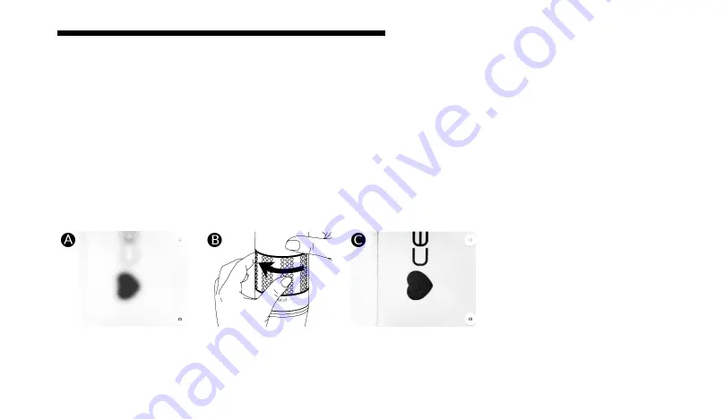
9. Manually adjust the focus knob until the target is in focus (Figure 8A and B). To focus objects closer to the camera, 
turn the focusing knob to the right (negative sign). To focus objects further from the camera, turn the focusing knob to 
the left (positive sign).

Figure 8:

 Focusing the HD Camera Toolhead on a test image.

Summary of Contents for BIO X HD Camera Toolhead

Page 1: ...BIO X HD Camera Toolhead User Manual...

Page 2: ......

Page 3: ...ad warnings 8 4 Getting started 9 4 1 Unpacking and installation 10 5 Initial calibration focusing and manual image capture 13 5 1 Your first image 14 5 2 Automated imaging during print 19 5 3 Removin...

Page 4: ......

Page 5: ...1 Package contents 01...

Page 6: ...2 01 Package contents Item Part number Quantity HD Camera Toolhead D16110020853 1 Lens cap D16110020652 1 Observation pad D16110022041 1...

Page 7: ...3 Technical specifications 02...

Page 8: ...mum field of view 7 4 x 5 5 mm Dimensions height x width x depth 35 4 x 127 5 x 46 6 mm Connection BIO X toolhead mount and mini USB Weight 235 g Material composition External surfaces Powder coated s...

Page 9: ...shown from the top and side view when using HD Camera Toolhead Movement range might be lower when combining the HD Camera Toolhead with a printhead that restricts printbox movement Please consult man...

Page 10: ...6...

Page 11: ...7 Safety information 03...

Page 12: ...ually will damage the motor If the mount needs to be moved place the toolhead in the loading position described in the Getting Started section Use the proper method to load and unload the HD Camera To...

Page 13: ...9 Getting started 04...

Page 14: ...ob 2 Body 3 Lens cap Open the package Remove the HD Camera Toolhead Remove the lens cap from the HD Camera Toolhead To insert the toolhead align the toolhead above a mount Figure 3A B and push downwar...

Page 15: ...11 04 Getting started Figure 3 Inserting the HD Camera Toolhead into a BIO X mount A B C D...

Page 16: ...hing the micro USB to the BIO X printbox Make sure the camera light turns on after the toolhead clicks onto the mount Figure 3D Connect the mini USB cord to the mini USB port on the printbox to enable...

Page 17: ...13 Initial calibration focusing and manual image capture 05...

Page 18: ...pture 5 1 Your first image 1 Ensure the HD Camera Toolhead is properly installed Section 4 2 Insert a USB flash drive in the BIO X 3 Go to the Move and Calibrate tab on the right side of the screen an...

Page 19: ...capture 4 Wait until the system has homed Ensure the HD Camera Toolhead is in the active position You can place the toolhead in the active position using the Tools tab on the Utilities menu Figure 6 F...

Page 20: ...with printed text 6 Go to the Camera tab on the right side of the screen 7 Press the movement commands icon on the top right side of the video feed to display the movement arrows Figure 7 Figure 7 A...

Page 21: ...ally adjust the focus knob until the target is in focus Figure 8A and B To focus objects closer to the camera turn the focusing knob to the right negative sign To focus objects further from the camera...

Page 22: ...e an image 11 This image will be stored on the USB flash drive with the name bio x screen capture png 12 Repeated captures will be saved with numbers at the end of the file name NOTE To include a scal...

Page 23: ...lhead is selected the Calibration tab will show the camera feed Figure 9 6 Position the toolhead in the desired print area and desired height above the construct The position should align with the oth...

Page 24: ...20 05 Initial calibration focusing and manual image capture Figure 9 Calibration of the HD Camera Toolhead...

Page 25: ...onnect the micro USB cable from the printbox to remove the HD Camera Toolhead Figure 10 2 Hold the mount in place with your hand and pull the toolhead up to remove it with the other hand See Section 3...

Page 26: ...22...

Page 27: ...23 Relevant G code commands 06...

Page 28: ...seconds and P is the wait time in milliseconds G7 Xnnn Ynnn Znnn Fnnn When used in combination with the G90 command which defines absolute coordinates G7 is the relative move command The values for t...

Page 29: ...image with a specific file name You can use the template below for writing a G code to take an image Please note that this is not a complete G code Tn sets HD Camera Toolhead in active position n is...

Page 30: ...26...

Page 31: ...27 Frequently asked questions 07...

Page 32: ...materials at a time when using the HD Camera Toolhead on the BIO X Can it take real time images The HD Camera Toolhead can capture images at points defined by G code The functionality is more limited...

Page 33: ...when capturing an image at the completion of a print Does it work independently or do I need to combine it with a printhead What if I want to image a previously printed construct The HD Camera Toolhea...

Page 34: ...30...

Page 35: ...31 Maintenance 08...

Page 36: ...solvents or strong detergents to clean the toolhead Wipe it with a soft cloth slightly dampened in a mild soap and water solution Regularly clean the printhead to remove any dust or debris Keep the c...

Page 37: ...33 Support information Official site Sales Store Support Official site www cellink com Contact support cellink com Contact sales cellink com Web store www cellink com store...

Page 38: ...www cellink com...

Reviews: