CEL-MAR ADA-4020A User Manual Download Page 12

ADA-4020A  converter with set up addressing is listening constantly to frame on RS485 bus via RS485/422 port. If received frame

contains byte of address equal to address of converter, then another bytes of frame are received, right up to silence on RS-485 bus

equal to 'space between frames in signs'. If the frame is received correctly, the address byte is deleted and transmitted over as typical

to the Current Loop port. In case of errors in received frame, it isn't transmitted to the Current Loop. In this case should be send the

previous frame one more. 
The frame received from device connected to Current Loop port is being tested of transmission errors and in case of their missing the

converter adds address to the beginning of frame and send it to RS485/422 bus through RS485/RS422 port. Frame containing errors

isn't being transmitted to RS485/422 port. In case of transmitting of frames containing more than 950 bytes converter receive only 950

bytes  and  next are  ignored.  ADA-  4020A  has   equipped  with  separate  buffers  for RS485/422  and  Current  Loop   CLO,  therefore

converter can operate in full duplex mode on RS-422 and RS-485 4-wire bus.
Additionally,   can   be   set   data   flow   control   for   RS485/RS422   interface   according   to   pt.   CONFIGURATION   BY   THE   USE   OF

ADACONFIG.
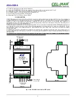
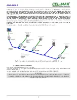
On a picture below are shown the possibilities of using the addressable ADA-4020A baud rate converter.

Fig.10. Connection of no addressable devices with Current Loop interface to RS485/422 bus

7. CHANGES IN THE SOFTWARE 

From CPU 2.0 and software 000.007 versions, was added:

- flow data control by the use of DE signal for RS485/RS422 interfaces. Description of using new option is in pt. CONFIGURATION BY

THE USE OF ADACONFIG,

- converter operating mode 

factory default

 is set by the use of SW1 micro-switch, see pt. OPERATING MODE

ATTENTION!!! 

THE SOFTWARE IN 0.007 VERSION AND UPPER WILL NOT OPERATE WITH THE CONVERTERS WITH CPU 1.0. VERSION.

IN CASE OF UPDATE THE SOFTWARE TO 0.007 VERSION AND UPPER IN THE CONVERTERS WITH CPU 1.0. VERSION

PLEASE CONTACT TO SERVICE.

12

ADA-4020A

RS-485 bus

2 - wires or 

4 - wires

Addressable 

device 

RS-485 

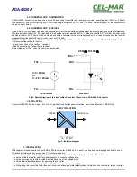
RS-485 bus parameters:

- baud rate 19200 bps,

- data bits 8,

- non parity,

- stop bits 2,

ADA-4020A

Address 3

CL

Current loop

ADA-4020A

Address 4

CL

Current Loop

Current Loop CL

device

ADA-4020A

Address 2

ADA-1040

RS-232

Current Loop CL

device

Current Loop CL

device

- baud rate 1200 bps,

- data bits 8,

- parity,

- stop bit 1,

Summary of Contents for ADA-4020A

Page 1: ...User manual ADA 4020A Addressable RS485 422 to Current Loop Baud Rate Converter 1 io_ada 4020a_en v 4 02 ADA 4020A Copyright 2001 2017 CEL MAR sp j...

Page 2: ...TO RS485 2 WIRES BUS 7 3 3 3 GND TERMINALS CONNECTION 7 3 3 4 LINE TERMINATION 7 3 3 5 CONNECTION OF CURRENT LOOP DEVICES 7 3 4 POWER SUPPLY 7 4 ACTIVATION 7 4 1 SIGNALING LEDS 8 5 CONFIGURATION 8 5 1...

Page 3: ...the assembly or dis assembly of the device if it is enabled This may result to short circuit and damage the device The device can not be used for applications that determine human life and health eg...

Page 4: ...baud rate up to 230 4 kbps via one or two pairs of twisted pair cables of RS485 422 interface and up to 38 4 kbps on 4 wires Current Loop bus ADA 4020A is equipped with screw terminal block for conne...

Page 5: ...connection of transmitter to receiver Review diagram of the receiver is shown on figure below Fig 2 Review diagram of the transmitter receiver Current Loop ADA 4020A Converter 2 5 ISOLATION Converter...

Page 6: ...as Tx A Tx B Rx Rx Below are shown connection of ADA 4020A converter to RS485 4W bus and RS485 2W bus 3 3 1 CONNECTION TO RS485 4 WIRES BUS Fig 6 Example connection of ADA 4020A to RS485 4 wires bus a...

Page 7: ...th current loop interface to ADA 4020A are shown on Fig 6 Fig 7 3 4 POWER SUPPLY The power supply to ADA 4020A should be DC regulated from the scope 10 V to 30V and nominal power more then 2W The powe...

Page 8: ...ly If after power on the front panel is not lit green LED PWR check the power connection polarity If the PWR LED lights set the section of SW1 switch to configuration mode as in table below SW1 1 SW1...

Page 9: ...ace operates in receiving transmitting data mode for RS485 bus 2 wires and 4 wires signal DE On RS485 RS422 interface operates in RS422 mode After configuration the setting should be saved on converte...

Page 10: ...as shown in the table below SW1 1 SW1 2 OFF OFF Yellow LED will be OFF 5 4 EMERGENCY FIRMWARE UPDATE In case of the unsuccessful update of the converter software try again according to description in...

Page 11: ...A 4020A converter s configuration and correctness connection of RS485 bus and Current Loop device to the converter ports After finishing the diagnostics the SW1 micro switch should be set to standard...

Page 12: ...duplex mode on RS 422 and RS 485 4 wire bus Additionally can be set data flow control for RS485 RS422 interface according to pt CONFIGURATION BY THE USE OF ADACONFIG On a picture below are shown the...

Page 13: ...ferences STP Nx2x0 5 24AWG 2 pair twisted cable UTP Nx2x0 5 24AWG shield inside large interferences STP Nx2x0 5 24AWG Transmission type Asynchronism full duplex half duplex Standards EIA 232 CCITT V 2...

Page 14: ...ryl UL 94 V O Degree of casing protection IP40 Degree of terminal protection IP20 Weight 0 10 kg According to standard DIN EN50022 DIN EN43880 Position during operation Free Mounting Rail mounting acc...

Page 15: ...15 ADA 4020A...

Page 16: ...transmission converters with interface RS232 RS485 RS422 USB Ethernet Wi Fi Current Loop Fibre Optic Converters and other Please contact us to tell how you like our products and how we can satisfy you...

Reviews: