
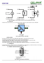

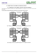


Fig 11. Example connection of ADA-1020 converters as Current Loop bus for 5 SLAVE converters
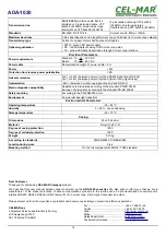
3.6. POWER SUPPLY
The power supply to ADA-1020 should be DC (regulated) from the scope 10 V= to 30V= (option from 10V= to 48V=) and nominal
power more 2W eg. DR15-24. The power cable from DC power supplies to the device must not be longer than 3m.
Observe the polarity, connect positive (+) of DC power supplies to V+ and negative (-) end to V- terminal.
ADA-1020 has the protection from opposite connection power supply. If after powering, on the front panel is not lit green LED PWR,
check the power connection (polarity).
4. ACTIVATION
Converter can be power on after proper connection according to steps above. If connection was made properly green LED PWR on
front panel of converter should light, if not check polarization of power connection and if RX red LED is lighted check the correctness
of connection of the Current Loop transmitter circuit. If RX red LED is continuously lit, the current is not flow through transoptor in the
receiver circuit. When data is present the LEDs Tx and Rx should blinking.
10
ADA-1020
G
N
D
R
S
23
2
C
u
rr
e
n
t
L
o
o
p
B
u
s
M
A
S
T
E
R
D
e
v
ic
e
M
o
d
em
G
S
M
.
.
R
x
T
x
S
L
A
V
E
-2
R
S
23
2
S
L
A
V
E
-5
R
S
23
2
RS232
ADA-1020-1-2-2-3
SLAVE-PASSIVE-1
S
L
A
V
E
-1
R
S
23
2
R
S
2
32
Rx+
Rx-
Rx+*
Tx+
Tx-
R
x-
T
x-
G
N
D
(
5)
R
x+
R
x+
*
T
x+
Rx+
Rx-
Rx+*
Tx+
Tx-
Rx+
Rx-
Rx+*
Tx+
Tx-
.
GND (5)
Tx (2)
Rx (3)
RS232
.
GND
Rx
Tx
RS232
.
T
x
(2
)
R
x
(3
)
R
S
2
32
D
B
9F
C
u
rr
e
n
t
L
o
o
p
A
D
A
-1
02
0
-1
-2
-2
-3
M
A
S
T
E
R
-A
C
T
IV
E
ADA-1020-1-2-2-3
SLAVE-PASSIVE-2
ADA-1020-1-2-2-3
SLAVE-ACTIVE-5
.
.
GND (5)
Tx (2)
Rx (3)
.
GND
Rx
Tx
.
GND (5)
Tx (2)
Rx (3)
.
GND
Rx
Tx
R
S
2
32
R
S
2
32
Current Loop
DB-9F
RS232
Current Loop
DB-9F
RS232
Current Loop
DB-9F
RS232


