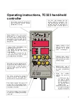


The “Out” light indicates that the
heating element is powered. The
“Aux” light indicates the status of an
auxiliary that can be associated to
the cycle steps or various types of
alarm.
______________________________________________________________________________________
Operating instructions, TC323 hand-held
controller
______________________________________________________________________________________
2
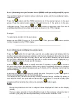
C h a n g e
Ti m e
° C
K W h
Fi x.
S p e c .
P e r s .
St e p
b y M ic r o P R O G E L
S P V
STO P
En t e r
STA R T
Se l e c t
P r o g .
These lights indicate the whether the
step in progress involves heating,
stabilisation or cooling.
Display (MAIN) of the main values
(temperature in °C, instant setpoint,
run time, partial and total energy
consumption). The four lights above
the display indicate which value is
being shown.
- Display (PRG or PROGRAM) of the
selected cycle, from 1 to 9.
- The “PERS.” light indicates that the
cycle belongs to the user group
(customisable).
- The “FIX” light indicates that the
cycle belongs to the group of cycles
pre-configured by the installer.
Display (STEP) of the
step in progress. If the
controller is in STOP
mode, “-“ is displayed.
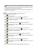
This button runs the selected cycle.
The light to the side indicates that the
control is active. To stop the cycle,
press the button again and hold for
half a second.
This button activates the delayed
running of a cycle. The delay time
can be set from 1 minute to 60 hours.
SCROLL button, used to
scroll through the values
that can be shown on the
«MAIN» display.
ENTER button, used to
confirm the value entered
in cycle programming
mode.
These two buttons
(arrows) are used as
follows:
-
in STOP mode, they
are used to select
the cycle from the 9
that are available in
the selected group
(PERS or FIX).
programming mode, they
are used to change
the time and setpoint
values.
This button selects the group of
cycles: user or pre-configured. Each
pressing of the button switches from
one group to the other.
This button accesses the procedure
for entering or modifying the selected
user cycle.


