


Installation and Troubleshooting Guide
This installation is to be completed by an Authorized Dealer or Professional Service
Technician. For questions regarding installation or warranty, call CDI Tech Support
at 866-423-4832. Do not return to the Dealer or Distributor where the part was purchased.
Contact CDI Electronics Directly for Return Material Authorization.
CDI Electronics, LLC
•
353 James Record Road SW
•
Huntsville, AL 35824 USA
Web Support: www.
•
Tech Support: 1-866-423-4832
•
Order Parts: 1-800-467-3371
All rights reserved. Reproduction or use of content, in any manner, without express written permission by CDI Electronics, LLC., is prohibited.
Rev E
•
4/30/2021 Page - 2 of 4 QF-358
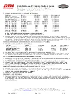
3. Check the resistance and DVA of the Stator and Trigger as follows:
Read from
Read to
OEM Ohms
CDI Ohms
DVA (Connected)
Blue (Low speed Coil)
Engine Gnd
5.0-7.0K
Ω
2-2.4K
Ω
180 V Minimum
Blue/White (Low speed Coil) Engine Gnd
5.0-7.0K
Ω
2-2.4K
Ω
180 V Minimum
Red (High speed Coil)
Engine Gnd
90-200
Ω
27-55
Ω
20 V Minimum
Red/White (High speed Coil) Engine Gnd
90-200
Ω
27-55
Ω
20 V Minimum
Brown (#1 Trigger) (a)
White (#4 Trigger) (b)
0.8-1.4K
Ω
0.8-1.4K
Ω
4 V Minimum
White (#3 Trigger) (a)
Purple (#6 Trigger) (b)
0.8-1.4K
Ω
0.8-1.4K
Ω
4 V Minimum
Purple (#5 Trigger) (a)
Brown (#2 Trigger) (b)
0.8-1.4K
Ω
0.8-1.4K
Ω
4 V Minimum
Brown (#1 Trigger) (a)
Engine Gnd
Open
Open
1 V Minimum
White (#3 Trigger) (a)
Engine Gnd
Open
Open
1 V Minimum
Purple (#5 Trigger) (a)
Engine Gnd
Open
Open
1 V Minimum
Brown (#2 Trigger) (b)
Engine Gnd
Open
Open
1 V Minimum
White (#4 Trigger) (b)
Engine Gnd
Open
Open
1 V Minimum
Purple (#6 Trigger) (b)
Engine Gnd
Open
Open
1 V Minimum
(a) Black Band- Inside Switchbox (Engines using studded Switchboxes)
(b) Yellow Band- Outside Switchbox (Engines using studded Switchboxes)
4. Check the DVA on the Green wires from the Switchbox while connected to the Ignition coils. Check the reading on the Switchbox
terminal AND on the Ignition coil terminal. You should have a reading of at least 150 V Minimum at both terminals. If the reading is low
on one cylinder, disconnect the Green wire from the Ignition coil for that cylinder and reconnect it to a Pack Load resistor. Retest. If the
reading is now good, the Ignition Coil is likely bad. A continued low reading symptom indicates a bad Switchbox.
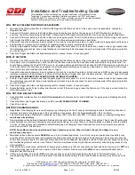
NO SPARK ON ONE BANK (ODD OR EVEN CYLINDERS ON INLINE 6 CYLINDER):
1. Check the resistance and DVA of the Stator as follows:
Read from
Read to
OEM Ohms
CDI Ohms
DVA (Connected)
Blue (Low speed Coil)
Engine Gnd
5-7K
Ω
2-2.4K
Ω
180 V Minimum
Blue/White (Low speed Coil)
Engine Gnd
5-7K
Ω
2-2.4K
Ω
180 V Minimum
Red (High speed Coil)
Engine Gnd
90-200
Ω
27-55
Ω
20 V Minimum
Red/White (High speed Coil)
Engine Gnd
90-200
Ω
27-55
Ω
20 V Minimum
2. Swap both sets of the Stator wires between the Switchboxes. If the problem moves, replace the Stator.
3. If the problem stays on the same bank, swap physical location and all connections of the two Switchboxes. If the problem stays with
one Switchbox, replace the Switchbox. If the Switchbox is bad, it is recommended that BOTH Switchboxes be replaced AS A SET.
ALL CYLINDERS HAVE SPARK BUT THE ENGINE WILL NOT RUN:
1. Check Ignition Timing for #1 Cylinder. Remember the Yellow banded leads go to cylinders 2, 4 & 6. and the Black banded leads go to
cylinders 1, 3, and 5. The Green Coil Primary leads could be swapped.
2. Index the flywheel for all cylinders. ALL Cylinders should have approximately the same Ignition timing offset as # 1 Cylinder.
3. Check the Resistance on each Switchbox’s White/Black wire, referenced to engine ground while disconnected. You should read
13-15 K
Ω
on each Switchbox. If there is over a 10% variance between the two Switchboxes, replace BOTH Switchboxes as a set.
4. Check Ignition Timing on
all
cylinders. If the Ignition Timing varies, replace
both Switchboxes as a set
.
SWITCHBOX OR TRIGGER REPEATEDLY BLOWS ON SAME CYLINDER:
1. Check the Trigger wires for shorts to engine ground as a shorted Trigger wire can destroy a SCR inside the Switchbox.
2. In contrast, a shorted SCR inside the Switchbox can destroy a Trigger coil. Check the Trigger resistance and DVA (see
NO SPARK OR
INTERMITTENT SPARK ON ONE OR MORE CYLINDERS
).
3. Replace the Ignition coil on the cylinder dropping spark.
ENGINE WILL NOT STOP (KILL):
1. Disconnect the Black/Yellow (or Orange) wire(s) at the Switchbox. Connect a jumper wire to the stop wire(s) from the Switchbox and
short it to engine ground. If this stops the Switchbox from sparking, the stop circuit has a fault. Check the key switch, harness, and shift
switch (if present). If this does not stop the Switchbox from sparking, replace the Switchbox. Repeat the test as necessary for any
additional Switchboxes.


