background image

fig. 5

fig. 3

fig. 4

11

11

600

min 

550

820- 

890

595

548

min 25

819- 

889

100- 170

5

6

11

11

Installation

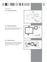
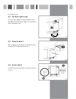
Fig. 3 -  Dimensions of the appliance

Fig. 4 -  Fitting the worktop bracket

Remove the screw (5) on the top of the appliance, locate the 
top bracket(6) and fix the bracket with screw(5).

Fig. 5 -  Fitting the spacer piece

Take out the spacer piece (11) located on the side panel and 
remove the protective tape. Stick the spacer piece on the 
opposite side to the door hinges of the appliance.

Summary of Contents for FW282 for

Page 1: ... The Group Ltd Harby Road Langar Nottinghamshire NG13 9HY T 01949 862 012 F 01949 862 003 E service cda eu W www cda eu Passionate about style FW282 integrated under counter freezer Manual for Installation Use and Maintenance ...

Page 2: ...r CE Declarations of Conformity This appliance has been designed constructed and marketed in compliance with safety requirements of EEC Directive 2006 95 EEC Low voltage and requirements of EMC Directive 2004 108 EEC This appliance has been manufactured to the strictest standards and complies with all applicable legislation including Electrical safety LVD and Electromagnetic interference compatibi...

Page 3: ...th wet hands Do not splash water onto the appliance Keep it away from places of high humidity that may have adverse effect on the electric insulation performance Please remove the door door seal and shelves before disposal of the old appliance and put them away in a safe place to prevent children from being entrapped Before first use You must allow the freezer to settle for at least twenty four ho...

Page 4: ...ity of the food after thawing Wrap food before putting into the freezer To stop the wrapping sticking together ensure it is dry Label the food before freezing with information including type of food and dates of storage and expiry Once food is thawed it must not be refrozen unless it has been completely cooked Only defrost as much food as is required to prevent wastage Bottled or canned drinks sho...

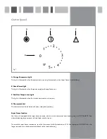
Page 5: ... is too warm D Thermostat dial The thermostat can be set between 0 least cold and 5 coldest Super Freeze function Your freezer is equipped with a super freeze function which runs the compressor continuously Super freeze should be used when introducing large amounts of fresh food into the freezer To switch the super freeze function on turn the thermostat dial fully clockwise to SF When the super fr...

Page 6: ...osted First remove the freezer drawers To speed up the process place a bowl of warm water in the base of the freezer compartment Once defrosting is complete dry the inside of the freezer compartment with a sponge or clean cloth The freezer should be cleaned using a solution of bicarbonate of soda and lukewarm water Do not use abrasive products or detergents After washing rinse and dry thoroughly C...

Page 7: ... working The temperature of the room is adequate 10o C or above The appliance is working but not very well The appliance is not overloaded The thermostat is set to an appropriate temperature The door is closing properly The cooling system at the rear of the appliance is clean and free of dust and not touching the rear wall There is enough ventilation at the side and rear walls The temperature of t...

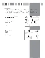
Page 8: ... worktop or kitchen carcass if a raised floor is to be fitted if the kitchen floor is to be tiled after installation or if the installation height of the appliance is greater than 850 mm Contents and Tools Required Fig 1 Installation kit contents 1 Wood screw 17 pcs 2 Decor door fixing bracket 3 Decor door base fixings 2 pcs 4 Decorative cover 5 Screw 6 Top bracket Fig 2 Tools required 7 Spirit le...

Page 9: ...ig 4 Fitting the worktop bracket Remove the screw 5 on the top of the appliance locate the top bracket 6 and fix the bracket with screw 5 Fig 5 Fitting the spacer piece Take out the spacer piece 11 located on the side panel and remove the protective tape Stick the spacer piece on the opposite side to the door hinges of the appliance ...

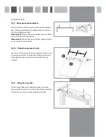
Page 10: ... fit the furniture height Use a spirit level to ensure the appliance is level Fig 7 Aligning the appliance Slide the appliance into the kitchen unit and align the hinge surface with front surface of the kitchen unit Fig 8 Fixing the appliance Screw the hinges and metal bracket to the kitchen unit using screws 1 fig 6 fig 7 7 7 8 9 1 1 ...

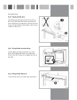
Page 11: ...the underside surface of kitchen unit to the top of next unit door Fig 10 Fitting the decor door bracket Substract C from B and put the fixing bracket 2 in place using this measurement for vertical position and place to the centre for horizontal position Secure the fixing bracket 2 using screws 1 Fig 11 Fitting the decor door Place the decor door onto the appliance door by inserting adjustment bol...

Page 12: ...s on the fixing bracket for other directions Lock the screws into place as shown in 10 2 Fig 13 Fitting the decor door base fixings With the appliance door open remove the screws at the bottom of the appliance door Locate the decor door base fixings 3 and screw the fixings to the appliance door and the decor door Fig 14 Fitting the decorative cover Fit the decorative cover 4 on the decor door fixi...

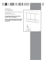
Page 13: ...mm gap between the cabinet door and fix it Never cover over the ventilation slots Once installed the plinth must not block the ventilation slots in the appliance This may require cutting the plinth down Failure to ensure adequate ventilation may invalidate the warranty fig 17 min 25mm ...

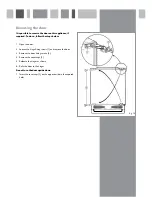
Page 14: ...s below 1 Open the door 2 Loosen the hinge fixing screws 1 and remove the door 3 Remove the door fixing screws 2 4 Remove the cover caps 3 5 Relocate the hinges as shown 6 Refit the door to the hinges Do not turn the door upside down 7 Insert the cover caps 3 on the opposite side in the exposed holes 2 fig 18 ...

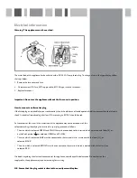
Page 15: ... to BS 1363 should be used As the colours of the wires in the mains lead of this appliance may not correspond with the coloured markings identifying the terminals in your plug proceed as follows The wire which is coloured GREEN and YELLOW must be connected to the terminal which is marked with letter E or by the Earth symbol or coloured GREEN and YELLOW The wire which is coloured BLUE must be conne...

Page 16: ...Group Ltd Harby Road Langar Nottinghamshire NG13 9HY T 01949 862 012 F 01949 862 003 E service cda eu W www cda eu Passionate about style To contact our Customer Care Department or for Service please contact us on the details below ...

Reviews: