background image

21

L

N

Green &Yellow
(Earth)

Brown
(Live)

Blue
(Neutral)

WARNING This appliance must be earthed

Figure 23

P

C

B

A

CONNECTING THE FEEDER CABLE

Remove the two screws that hold shield A behind the oven.

Open completely the cable clamp C

Insert the feeder cable (type H05 RR-F) of minimum 6 mm

2

section into the cable

save P.

Connect the phase and earth cables to terminal B according figure 23.

The wires of this appliance must be coloured in accordance with the following code:
GREEN AND YELLOW - EARTH
BLUE - NEUTRAL
BROWN - LIVE
The wire which is coloured GREEN AND YELLOW must be connected to the terminal
in the plug which is marked with the letter “E” or by the Earth 

symbol or coloured

GREEN or GREEN AND YELLOW.

The wire which is coloured BLUE must be connected to the terminal which is marked
with the letter “N” or coloured BLACK.
The wire which is coloured BROWN must be connected to the terminal which is
marked with the letter “L” or coloured RED.

Pull the feeder cable and block it with the cable clamp C.

Re-mount shield A.

REPLACING THE POWER SUPPLY CABLE

Use the same type of power supply cable.

Summary of Contents for CD 900

Page 1: ...Double Ovens CD 900 CD 906 Before operating this oven please read these instructions carefully Users Operating Instructions...

Page 2: ...d built by our specialist staff and thoroughly tested to satisfy your cooking requirements We suggest that you read this Instruction Booklet so that you will understand fully how to operate your appli...

Page 3: ...commended that all potentially hazardous parts be made harmless WARNING This appliance should only be installed by an authorised person of suitable qualification This appliance must be used only for t...

Page 4: ...neutral detergent and dry thoroughly Hang the wire racks on the oven sides Figure 1a and 1b Slide in on the guides the shelf and the tray etc Figure 2 To eliminate traces of grease from the heating el...

Page 5: ...radiation The heat is irradiated by the infra red grill element BOTTOM OVEN GENERAL FEATURES This is a fan oven with 2 cooking options thermostatically controlled BOTTOM OVEN OPERATING PRINCIPLES Hea...

Page 6: ...6 A U T O Thermostat Temperature light Temperature light Function selector Thermostat Function selector Digital electronic programmer Bottom oven only Figure 3 Double oven Models CD 900 CD 906...

Page 7: ...ooking both inside and out for example roasts spare pork ribs meringues etc FUNCTION SELECTOR KNOB fig 5 Rotate the knob clockwise to set the oven for one of the following functions OVEN LIGHT By sett...

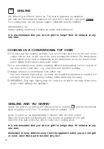
Page 8: ...the appliance GRILLING AND AU GRATIN Switch the grill on by setting the selector knob to position and the thermostat knob to position 225 C for 15 minutes then to position 175 C Leave to warm up for...

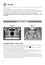
Page 9: ...s the selected temperature The light will cycle on and off during cooking in line with the oven temperature FAN OVEN Use in conjunction with the temperature selector It is advisable to pre heat the ov...

Page 10: ...ntional static system therefore the temperature should be set 15 C 20 C below those recommended in your recipe books The oven door should only be opened briefly while cooking so any heat losses are qu...

Page 11: ...owning meals after ordinary cooking The oven is supplied with two grill pan handles which clip on to the grill pan The handles must be removed before closing the oven door We recomend that you use ove...

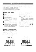
Page 12: ...h programme inserted Automatic cooking taking place Timer in operation and AUTO flashing Programme error The time of day lies between the calculated cooking start and end time Note Select a function b...

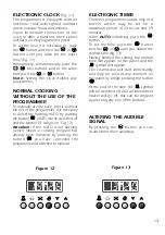
Page 13: ...l you obtain the desired time fig 13 Having finished the setting the normal time will appear on the panel and the symbol will appear The countdown will start immediately and may be seen at any moment...

Page 14: ...n this case modify the end of cooking time or the cooking time itself by following the above instructions again 3 Set the temperature and the cooking programme by using the switch and thermostat knobs...

Page 15: ...temperature and the cooking programme using the oven switch and thermostat knobs see specific chapters The oven is switched on and it will be switched off automatically at the end of the desired time...

Page 16: ...or tomato juice to remain in contact with the enamel parts as they may stain or discolour the surface If any cleaners such as a spray or a stick are used on enamel they must have the VEDC Vitreous Ena...

Page 17: ...Grip the door as indicated in fig 20 and while closing it release the two hinges as shown in fig 21 REASSEMBLING THE OVEN DOOR Grip the door with your hands placed near the hinges and raise the lever...

Page 18: ...ll food containing fat without using the grid Do not cover the grilling grid with aluminium foil Do not use the oven tray for roasting Do not clean the oven without first turning off the electricity s...

Page 19: ...ppliance is ventilated by means of the space in the top of the kitchen cabinet Lift the appliance into position onto the shelf taking care NOT to lift it by the door handles If you lower the oven door...

Page 20: ...Double pole switch The power supply cable must not touch the hot parts and must be positioned so that it does not exceed 75 C at any point Once the oven has been installed the switch or socket must al...

Page 21: ...with the following code GREEN AND YELLOW EARTH BLUE NEUTRAL BROWN LIVE The wire which is coloured GREEN AND YELLOW must be connected to the terminal in the plug which is marked with the letter E or by...

Page 22: ...4 66 kW Top oven Conventional Top element 700 W Grill element 2100 W Botton element 1100 W Bottom oven Multifunction Grill element 2500 W Fan element 2500 W CDA continually strive to improve our produ...

Page 23: ...23...

Page 24: ...1101401 6 Double Oven...

Reviews: