RSA-107 Installation and Operation Manual
2
© 2010 CBS ArcSafe
®
2010-12-23
1.0 Components
The Remote Switch Actuator (RSA-107) consists of a rotating arm attached to a gear motor. When
power is applied from the remote switch operator (RSO-1), the RSA-107 gear motor transmits the
rotary motion to the shaft and arm tool. This motion operates the rotary switch to the desired
position before coming to rest against a hard stop. In order for the RSA-107 to function optimally, it
must be properly adjusted either by CBS ArcSafe® prior to delivery or on-site by a qualified technician.
2.0 Installation
1.
Ensure the motion of the RSA-107 arm is properly adjusted to the rotary
switch to be operated. Adjust either the thumbscrew depth or the blue
hard stop on the opposite side to set the length of the arc of travel.
2.
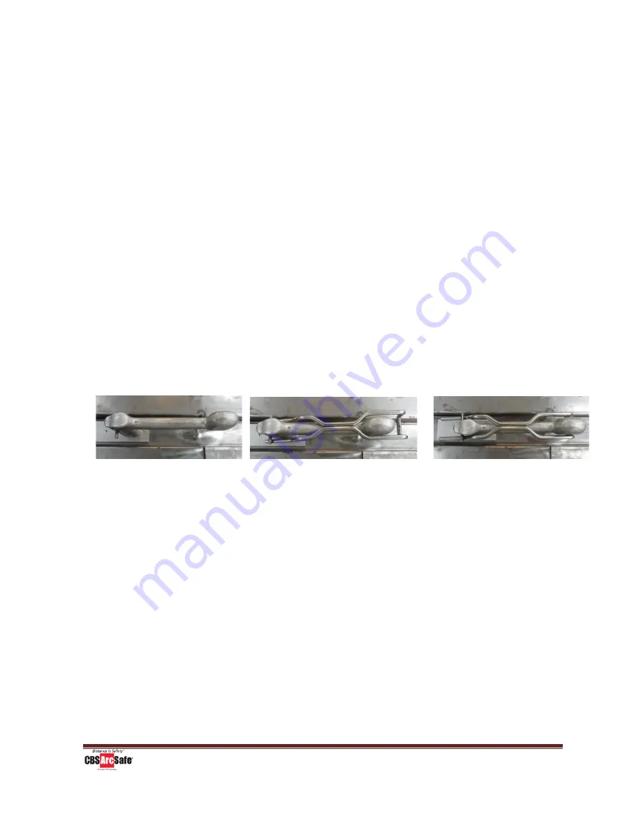
Attach the interlock defeat to the switch. Follow the steps in the pictures
to attach the interlock defeat.
3.
If the RSA-107 is being installed on a closed switch, press and hold the
“CLOSE” button before operating. If the RSA-107 is being installed on an
open switch, press and hold the “TRIP” button before operating.
4.
Install the RSA-107 on the switch to be operated. The hard stop on the
upper magnet should rest on the top of the switch housing. Ensure that
the motor shaft aligns with the handle shaft.
5.
Secure the two twist lock magnets to the switch. Ensure the magnets on
the RSA-107 mounting brackets are fully seated on the cabinet.
6.
Attach the RSA-107 to the remote switch operator (RSO-I) by connecting
and securing the four pin connector on the control box to the RSO-I cable.
Ensure switch is in interlocked position
Slide forks under the interlock roll pin
and push down on the rear
Slide rear under handle and push forward
until roll pin reaches the bend


