Page 11
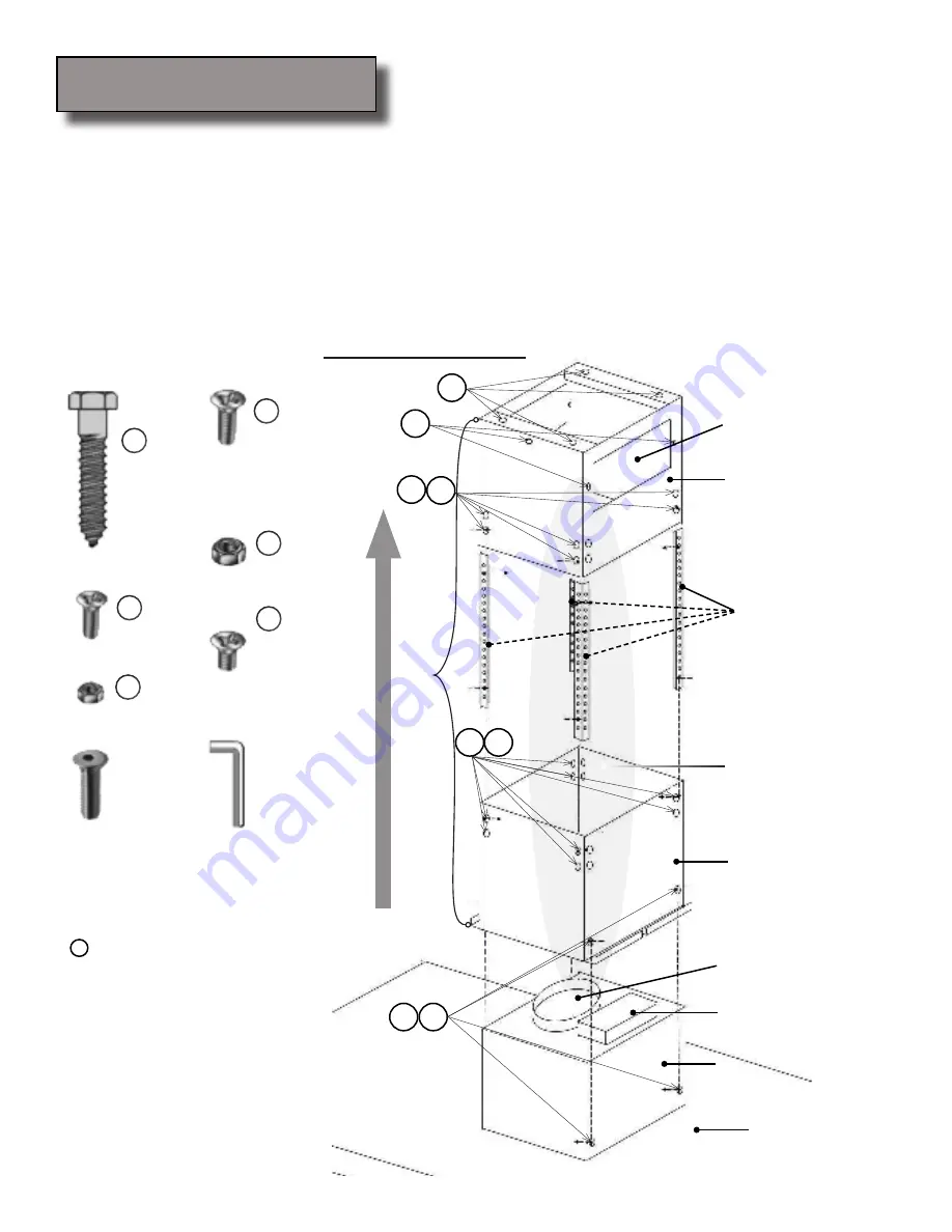
Have a third person raise up and hold the island range hood in position, connect power plug to the 12” hanging
9.
electrical cord, and connect the duct work to the range hood.
Mount the hood to the lower support frame using four “D” bolts and four “E” nuts: Securely fasten two “E”
10.
nuts to two “D” bolts by reaching up from the underside of the hood. Repeat this step to secure the other side
using two “E” nuts to two “D” bolts.
After all four “D” bolts and four “E” nuts securely fastened, connect the lower end of the duct tube to the hood
11.
and slide the lower chimney cover down carefully so that it sits on top of the hood.
Install grease cup and aluminum filters then check the operation of the range hood.
12.
Air Movement Direction
Upper support frame
Support frame extensions
(Hole to hole distance:
≈
⅝
-inch)
Island mount
range hood
Lower support frame
Motor housing
Electric circuit box
6” Round duct (exhaust)
Re-circulating kit exhaust
(Re-circulating kit not shown)
Duct work and electric
wiring region
A
B
C
D
E
F
Installation Overview
B
C
Qty: 4 PCS
A
Qty: 32 PCS
B
Qty: 4 PCS
D
Qty: 32 PCS
C
Qty: 4 PCS
E
Qty: 4 PCS
(Optional with
re-circulating
kit. Pre-installed
when kit ordered
together with
range hood)
F
Hex Key
Qty: 1 PCS
(Optional with glass canopy)
Glass Canopy Screw
Qty: 4 PCS
(Optional with glass canopy)
Installation
(Continued)
NOTE:
screws are designed for dry wall.
•
Not to be used with any other types
of walls.
A distance of 28” to 31” is recom
-
•
mended* between stove top and the
bottom of range hood.
Always use first and second holes
•
on the support frame extensions to
secure lower support frame.
*
Due to different ceiling height configu
-
rations, recommended height may not be
applicable.
IMPOR
TANT
: Minimum height = Longest c 1½-inch
A
Summary of Contents for 218 Series
Page 2: ......
Page 18: ...Page 16 Wiring Diagram Six Speed with Type GU10 Bulb Six Speed with Type MR16 Bulb ...
Page 22: ...Your Notes Page 20 ...
Page 23: ...Your Notes Page 21 ...


