background image

Remtron

®

 Patriot 

User Manual 


15 

9M02-9028-A001-EN 
Rev 12 


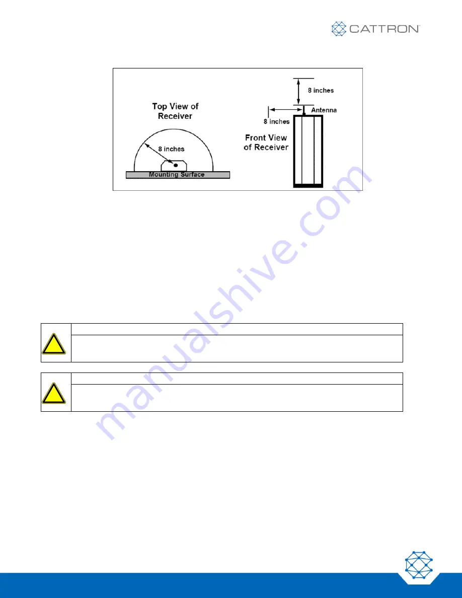
Figure 4: Antenna Clearance 

6.2.2  Receiver Location 

To ensure safe and reliable system operation, the following items must be considered when selecting a location 
for mounting the receiver: 


Install the receiver in an environment where the ambient temperature during operation does not drop 
below -20º F (-28º C) or rise above +160º F (+71º C) 


To ensure that the receiver enclosure is electrically at earth ground, connect the green wire in the 
interface cable to earth ground 


Mount the receiver enclosure securely using appropriate locking-type hardware 

6.3 

Installation Wiring 


WARNING


Before starting this installation, ensure that the crane power has been disconnected and that all 
applicable safety precautions are followed. 


CAUTION


Connection to equipment or contactors with higher voltage or current requirements requires 
intermediate relays. 

6.4 

Output Snubbers 

Snubbers are recommended for the suppression of noise generated from arcing relay contacts. When a contactor 
opens, the contactor coil produces a large voltage potential, much like automotive ignition systems. When the 
points open on automotive ignition systems, the coil sends a large voltage to the distributor. This voltage jumps 
across the spark plug (called 

arcing

). The result is a large amount of noise generated in the system.  

A snubber is a device designed to reduce arcing (noise). To increase relay life, it is recommended that all 
contactors have snubbers installed directly across the coils. If more snubbers are needed, see the 

Receiver 

Spare Parts List

 or contact Cattron at 

www.cattron.com/contact

 .


!

!

Summary of Contents for Remtron Patriot 25R15A

Page 1: ...Remtron Patriot User Manual 9M02 9028 A001 EN ...

Page 2: ...as to non infringement nor as to the fitness merchantability or sustainability of any Cattron products for any specific or general uses Cattron Holdings Inc or any of its affiliates or agents shall not be liable for incidental or consequential damages of any kind All Cattron products are sold pursuant to the Terms and Conditions of Sale a copy of which will be furnished upon request When used as a...

Page 3: ... Frequency 10 5 1 2 Range and Antenna Coverage 10 5 1 3 License Free Channels 10 5 1 4 Command Format 11 5 1 5 Safety 11 5 2 Transmitter Operation and Features 11 5 3 Operation 12 5 4 Commands 12 5 4 1 Command Switches 12 ON ALARM 12 OFF STOP 12 A B SWITCH 12 AUTO OFF 12 5 5 Status Indicators 12 5 5 1 Status LED 12 5 5 2 Function Select LEDs 13 6 Installation 14 6 1 General 14 6 2 Locating the Equ...

Page 4: ...shooting 19 7 4 1 Normal Operation 20 7 4 2 Replacing the Transmitter Batteries 20 7 4 3 Changing the Transmitter ID Code 21 7 4 4 Transmitter Spare Parts List 21 7 5 Receiver Troubleshooting 22 7 5 1 General 22 7 5 2 Receiver Testing 22 7 5 3 Receiver Repairs 23 7 5 4 Fuse Replacement 23 7 5 5 Receiver Spare Parts List 24 8 Warranty Statement 25 9 CE Declaration of Conformity 25 Appendix I Transm...

Page 5: ...The remote control system you have purchased is designed to stop in a safe mode under a variety of conditions Some examples of these conditions are excessive radio signal interference loss of battery or electrical power failure of certain components operation beyond signal range and others Although Cattron and its subsidiaries do not specify the position of the operator when controlling the equipm...

Page 6: ...l it may cause harmful interference to radio communications However there is no guarantee that harmful interference will not occur in a particular installation If this equipment does cause harmful interference to radio or television reception which can be determined by turning this equipment on and off the user is encouraged to try to correct the interference by one or more of the following measur...

Page 7: ... heat in excess of 160º F DO NOT INSTALL IN HIGH VIBRATION AREAS The life of this apparatus may be shortened through long exposure to intense shaking or vibration 3 2 Personal Safety MAKE SURE MACHINERY IS CLEAR BEFORE OPERATING Do not activate the remote system unless it is safe to do so TURN OFF THE RECEIVER POWER BEFORE WORKING ON MACHINERY Always disconnect the remote system before doing any m...

Page 8: ...f applications for the systems Many new features have been added but most changes are transparent to the user If you are already familiar with Cattron transmitters you are encouraged to read the section on operating the transmitters where you will find information about the latest changes in operation To help you identify your system Figure 1 and Figure 2 provide a reference for the transmitters a...

Page 9: ...Remtron Patriot User Manual 9 9M02 9028 A001 EN Rev 12 Figure 2 Cattron Patriot Receivers ...

Page 10: ...They can send and receive in all directions or in a single direction depending on their design An omnidirectional antenna is like a light bulb and a directional antenna is like a flashlight Metal objects reflect radio waves just as a mirror next to a light bulb will reflect light Metal objects near an antenna alter the intended pattern of an antenna by either shading or reflecting signals Our stan...

Page 11: ...de for each user There are provisions in the system for 65 535 individual codes Each transmission includes a CRC check sum which is a polynomial created by factoring all of the previous bits transmitted Once the receiver receives a valid start command from the transmitter the receiver tracks the time of the transmitter and ignores all other transmissions that do not fall within the expected time f...

Page 12: ...n the transmitter and puts the system in the active mode It sends an ALARM command to the receiver while the switch is depressed The transmitter will remain active until the OFF STOP button is pressed or the transmitter switches itself off see Auto Off OFF STOP While depressed this button sends a STOP command to the receiver The transmitter does not need to be switched ON to send this command When...

Page 13: ...ting low change batteries at the next convenient opportunity LED flashes On Off at a slow rate second on and second off Batteries getting low change batteries at the next convenient opportunity LED remains on continuously LED might flicker slightly A switch was activated at the time the transmitter was switched on or a general failure occurred that requires factory service Ensure no other switches...

Page 14: ...nna is one of the most important components of a radio receiving system Proper placement of the receiver antenna ensures reliable operation under the most severe conditions A direct line of sight path between the transmitter and receiver antenna provides best performance refer to Figure 3 Figure 3 Transmitter Receiver Communication In most cases the antenna may be mounted directly on the receiver ...

Page 15: ...isconnected and that all applicable safety precautions are followed CAUTION Connection to equipment or contactors with higher voltage or current requirements requires intermediate relays 6 4 Output Snubbers Snubbers are recommended for the suppression of noise generated from arcing relay contacts When a contactor opens the contactor coil produces a large voltage potential much like automotive igni...

Page 16: ...he ML Coil when the transmitter is active If a pendant is also connected to the controls we recommend the addition of a transfer switch to select either pendant or radio control 5 Connect the remainder of the wires to the control relays as required Note The standard Patriot receiver can interface to either 3 or 4 wire hoist controls When installing the Patriot on standard 3 wire hoist controls the...

Page 17: ...Remtron Patriot User Manual 17 9M02 9028 A001 EN Rev 12 Figure 5 Patriot Receiver 25R15A ...

Page 18: ...Remtron Patriot User Manual 18 9M02 9028 A001 EN Rev 12 Figure 6 Connections and Labels for Patriot Receivers ...

Page 19: ...nd to the transmitter Wrong transmitter code Make sure transmitter is the correct one for the receiver Re program the transmitter Transmitter problem See Transmitter Troubleshooting Receiver problem See Receiver Troubleshooting System has short range Antenna placement Move the antenna See Antenna Location Antenna cable shorted or open Check cable and connections to the antenna Some functions are i...

Page 20: ... getting low change batteries at the next convenient opportunity LED remains on continuously LED might flicker slightly A switch was activated at the time the transmitter was switched on or a general failure occurred that requires factory service Ensure no other switches are pressed while attempting to switch the transmitter on LED will not light when ON OFF button is pushed Replace batteries If t...

Page 21: ...he keypad and press the PRG key The RAC16A display should read SUCCESS 6 Remove the batteries from the transmitter 7 After replacing the back panel reinstall the batteries and battery door A Series captive screws should be tightened until snug plus half a turn See the RAC16A Series User s Manual for more detailed instructions 7 4 4 Transmitter Spare Parts List Item Part Number Spare Transmitter co...

Page 22: ...e decoder s address when this LED flashes MLC should be active OUTPUT One or more command outputs are energized when this LED is lit not including MLC relay 7 5 2 Receiver Testing Follow these steps when troubleshooting the Patriot receivers 1 Check the POWER LED If this LED is not lit Check that the power source to the receiver is present If 115 VAC is present between the WHT and BLK wires on the...

Page 23: ... 3 Receiver Repairs Patriot receivers have been designed for the utmost reliability Other than two fuses to protect the basic power circuits there are no serviceable items in the receiver 7 5 4 Fuse Replacement See Figure 8 1 Ensure power is switched OFF to all receiver power inputs 2 Remove the mounting bolts from the end of the receiver by the interface cable 3 Remove the four screws on the end ...

Page 24: ...se Model No Receiver Antenna 485026 Snubbers 115 240 AC 600052 Antenna Cable Assembly w SMB and panel mount TNC connectors 920040 01 Antenna Mounting Kit w angle bracket 9 coax cable and connectors 600038 01 Antenna Mounting Kit w angle bracket 18 coax cable and connectors 600038 02 250 mA 250V fuse 485030 10A 125V fuse 458028 Transfer Switch 452031 ...

Page 25: ...arranty Statement For service and repairs go to www cattron com contact 9 CE Declaration of Conformity Hereby Cattron declares that the radio equipment is in compliance with Directive 2014 53 EU View the EU Declaration of Conformity document at www cattron com ...

Page 26: ...irements for license free operation Antenna Circuit board internal Indicators Self test LED indicator Ambient Operating Conditions 20º F to 160º F 28º C to 71º C Model Weight 1 Dimensions Commands Batteries 25T08A 10 9 oz 2 75 x 7 11 x 1 22 8 2 25T10A 10 9 oz 2 75 x 7 11 x 1 22 10 2 25T11A 12 9 oz 2 75 x 8 48 x 1 22 11 2 25T15A 12 9 oz 2 75 x 8 48 x 1 22 15 2 Notes 1 Weight includes Alkaline batte...

Page 27: ...Decoder Microprocessor controlled Command Functions 25R11 Up to 11 25R15 Up to 15 Response Time 60 Milliseconds Safety Features Address check CRC code check Format test Signal check Transmitter status checks Self test Indicators LEDs for easy troubleshooting Output Contacts 8 A 230 VAC Logic Base Programmable for each application Power Requirements 115 VAC 1 phase 50 60Hz Maximum Current Drain 0 1...

Page 28: ...he information provided in this document is subject to change without notice Cattron Support For remote and communication control systems support parts and repair or technical support visit us online at www cattron com contact Cattron North America Inc 655 N River Rd NW Suite A Warren OH 44483 ...

Reviews: