STEP 4
Parts Required:
Quantity
Part Description
4
Nut (Black plastic M3 thread)
1
Flight Controller
*
Not included and sold separately
*
Assembly Process:
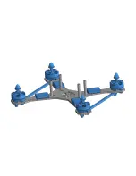
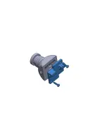
Make all the necessary electrical connections to the PDB and FC, then install the FC as shown. Make sure to orient the
FC's USB port so it is accessible. Ideally, you should direct solder the ESC signal wires to the FC. The use of ESC signal wire
right angle pin headers may be possible, however this will not leave much room for your other components.
Summary of Contents for Speed Addict SuperLight
Page 1: ...C O N T E N T S 01 BILL OF MATERIAL 02 REQUIRED TOOLS 03 ASSEMBLY PROCESS...
Page 2: ...SECTION 01 BILL OF MATERIAL...
Page 5: ...SECTION 02 REQUIRED TOOLS...
Page 7: ...SECTION 3 ASSEMBLY PROCESS...
Page 9: ......
Page 10: ......
Page 11: ......
Page 13: ......
Page 14: ......
Page 15: ......
Page 16: ......
Page 17: ......
Page 19: ......
Page 20: ......
Page 21: ......
Page 22: ......
Page 24: ......
Page 25: ......
Page 27: ......
Page 28: ......
Page 29: ......
Page 30: ......
Page 31: ......
Page 33: ......
Page 34: ......
Page 35: ......
Page 36: ......
Page 38: ......
Page 39: ......
Page 40: ......
Page 41: ......
Page 42: ......
Page 43: ......
Page 44: ......
Page 45: ......
Page 47: ......


