CAT Pumps 2530 Service Manual Download Page 2

SERVICING THE VALVES

Disassembly

1. To service the Valves, the Discharge Manifold must be re-

moved. Using a M10 allen wrench remove the eight
Socket Head Screws.

2. Support the underside of the Discharge Manifold and

lightly tap the top back of the manifold with a soft mallet.
Two screwdrivers may be needed to further separate the
Discharge Manifold from the Inlet Manifold.

3. Remove the Discharge Manifold and place it crankcase

side up.

NOTE: The Discharge Valve Assembly is secured in
the upper chambers by the Discharge Valve Spacer,
while the Inlet Valve Assembly is secured in the lower
chambers by the Inlet Valve Adapter.

4. The Discharge Valve Spacers will remain in either the

Inlet Manifold or the Discharge Manifold. To remove the
Spacer from the manifold, insert two screwdrivers on 
opposite sides under the machined lip on the outside of
the Spacer and pry out.

5. Use a reverse pliers to remove the Inlet Valve Adapters

from the Discharge Manifold or insert two screwdrivers
into the secondary groove on opposite sides of the
adapter and pry from valve chamber.

6. Both the Inlet and Discharge use the same Valve

Assembly. With a flat head screwdriver, carefully pry 
the Seat, O-Ring, Valve, Spring and Retainer from the
manifold chamber.

CAUTION: Exercise caution to avoid scoring the 
manifold chamber wall.

NOTE: This Valve Assembly does not snap together.

Reassembly

NOTE: For certain applications apply liquid gasket to
the O-Ring crevices and seal surfaces. See Tech
Bulletin 053 for model identification.

NOTE: EPDM elastomers require a silicone-base 
lubricant.

1. Inspect the Spring Retainer for any scale buildup or wear

and replace as needed. Place the Spring Retainer into the
valve chamber.

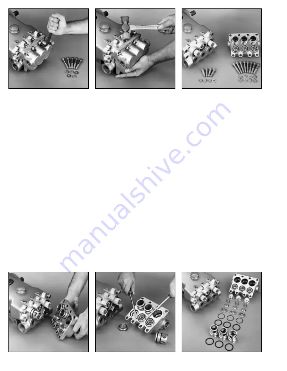
Removal of Discharge Socket Head Screws

Separation of Discharge Manifold from Inlet Manifold

Discharge Manifold with both Inlet Valve Adapters and
Discharge Valve Spacers.

Removal of Discharge Valve Spacers

Removal of Inlet Valve Adapters

Discharge Valve Assembly

CAUTION: Before commencing with service, shut off drive (electric motor, gas or diesel engine) and turn off water supply to
pump. Relieve all discharge line pressure by triggering gun or opening valve in discharge line.

After servicing is completed, turn on water supply to pump, start drive, reset pressure regulating device and secondary valve, read
system pressure on the gauge at the pump head. Check for any leaks, vibration or pressure fluctuations and resume operation.

Summary of Contents for 2530

Page 1: ...estricting orifice The pump is rated for a maximum pressure this is the pressure which would be read at the discharge manifold of the pump NOT AT THE GUN OR NOZZLE Use PTFE thread tape or pipe thread sealant sparingly to connect accessories or plumbing Exercise caution not to wrap tape beyond the last thread to avoid tape from becoming lodged in the pump or accessories This condition will cause a ...

Page 2: ...me Valve Assembly With a flat head screwdriver carefully pry the Seat O Ring Valve Spring and Retainer from the manifold chamber CAUTION Exercise caution to avoid scoring the manifold chamber wall NOTE This Valve Assembly does not snap together Reassembly NOTE For certain applications apply liquid gasket to the O Ring crevices and seal surfaces See Tech Bulletin 053 for model identification NOTE E...

Page 3: ...replace 7 Fit the O Rings into both the outer groove and face groove of the Inlet Adapter and apply liquid gasket into the O Ring crevice 8 Press the Inlet Adapter into the lower manifold chamber 9 Remove and examine both O Rings on the Discharge Valve Spacer for wear or cuts and replace as needed 10 Fit the new O Rings into the groove on the outside of the Discharge Valve Spacer Apply liquid gask...

Page 4: ... Seal and carefully press it into the Inlet Manifold chamber with the metal side down SERVICING THE PLUNGERS Disassembly NOTE The Ceramic Plungers and the Plunger Retainers should be examined on the same schedule as servicing the seals 1 To service the Ceramic Plungers first remove the Seal Retainers 2 Loosen the Plunger Retainer about three or four turns using a M14 hex tool 3 Grasp the Ceramic P...

Page 5: ...arefully press the Discharge Manifold into the Inlet Manifold Use a soft mallet to tap into place and reinstall the eight Socket Head Screws Torque in sequence to specifications in torque chart TORQUE SEQUENCE SERVICING THE CRANKCASE SECTION 1 While Inlet Manifold Plungers and Seal Retainers are removed examine Crankcase Oil Seals for leaking and wear 2 Check for any signs of leaking at Rear Cover...

Page 6: ...hose NOT a rigid pipe and reinforced on SUCTION systems to avoid collapsing The simpler the inlet plumbing the less the potential for problems Keep the length to a minimum the number of elbows and joints to a minimum ideally no elbows and the inlet accessories to a minimum Use pipe sealant to assure air tight positive sealing pipe joints INLET PRESSURE should fall within the specifications of the ...

Page 7: ...34 10 4 6 220 52 16 7 1 8 300 80 25 10 2 10 450 120 38 14 3 15 900 250 80 30 7 20 1600 400 121 50 12 25 650 200 76 19 30 250 96 24 40 410 162 42 50 600 235 62 60 370 93 At a fixed flow rate with a given size hose the pressure drop across a given hose length will be directly proportional A 50 ft hose will exhibit one half the pressure drop of a 100 ft hose Above values shown are valid at all pressu...

Page 8: ... precharge If low recharge or install a new dampener Foreign material trapped in inlet discharge valves Clean inlet discharge valves or install new valve kit Water leak Under the manifold Worn High Pressure or Lo Pressure Seals Install new seal kit Increase frequency of service Worn adapter o rings Install new o rings Into the crankcase Humid air condensing into water inside the crankcase Install ...

Reviews: