Cast Tec Integra HE Installation And User Instructions Manual Download Page 1

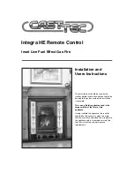
Integra HE Remote Control

Inset Live Fuel Effect Gas Fire

Installation and

Users Instructions

These instructions should be read by the

installer before installation and then should be

handed to the end user when the installation

is complete.

This is an official requirement and is the

responsibility of the fitter of this

appliance.

Having installed the appliance, the installer

should take the necessary steps to ensure

that the user fully understands how to operate

the appliance and is also made aware of the

fire’s basic cleaning and maintenance

requirements.

Summary of Contents for Integra HE

Page 1: ...be handed to the end user when the installation is complete This is an official requirement and is the responsibility of the fitter of this appliance Having installed the appliance the installer shou...

Page 2: ...d 22 x 16 5 Installation Procedure Decorative Cast 7 Commissioning 8 Technical Data 8 Replacement Parts 8 Trouble Shooting GAS SAFE Engineer Only 9 User Instructions 12 Cleaning and Maintenance 17 Fir...

Page 3: ...ration The installer must then establish that all the products of combustion are entering the flue within ten minutes of lighting from cold This can be verified by inserting a lit smoke match into the...

Page 4: ...ness of the flue and to ensure that there is no leakage into another part of the premises including any loft or as appropriate other adjoining premises this is particularly important where a number of...

Page 5: ...and stick a continuous strip down the two sides and across the top of the radiant box When the box is placed against a flat surface the foam strip will form a seal around the boxes flange 7 Carefully...

Page 6: ...yed using the optional cable fixing kit provided Drill four holes in the rear of the fireplace opening Fig 7 Securely fix the four eye bolts provided using suitable rawl plugs Feed one cable through e...

Page 7: ...ear of the radiant box When the box is placed against the cast surround the foam strip will form a seal around the boxes flange 4 Lift the fire box on to the two studs at the top of the surround and c...

Page 8: ...er Ref LEG59 5 Glass Rope Seal The integrity of the glass rope seal should be checked on service and replaced if necessary by a Gas Safe Registered Engineer Order Ref LEG58 COMMISSIONING 8 Gas Type Na...

Page 9: ...erform a restart to reset error display to normal standby mode Also depending upon the repair air will need to be bled out of the system and it may take several start attempts to do so E00 may appear...

Page 10: ...h Reset and try again Check pressure switch connections check to see if jumpers are in place on back of TESC E09 Error caused by external pressure switch Pressures switch action connection or jumpers...

Page 11: ...ect type E26 Defective or wrong wired USB power supply Try again and if repeatedly fails replace Reset and try again Check and correct Thermocouple wiring Replace thermocouple if necessary E48 Short c...

Page 12: ...position I To start the fire press the power button and hold for 1 second then release The burner will light within around 1 to 10 seconds adjust to the maximum power setting The power of the burner...

Page 13: ...ss to increase flame Day of the week Gas fire burner status Battery condition RC handset FC fire control Light sensor for display backlight To change mode see handbook Press to decrease flame Power bu...

Page 14: ...time to set the timer to either 24 hour display or 12 Hour AM or PM display Press the or button on the handset to toggle between the two settings When you are ready to confirm the setting you want pre...

Page 15: ...on to toggle between modes Note If at any time the power button is pressed during operation this will stop the fire and exit any automatic mode and return the handset to manual MAN operation mode Fact...

Page 16: ...d in an earlier section snooze function can also be operated in conjunction with thermostat mode The thermostat symbol and the Zzz symbol will be on together when in this mode The remote control displ...

Page 17: ...nd the pilot assembly Any build up of debris in this area could affect the operation of the appliance Fig 21 NOTE It is common to find surface cracks in the ceramic components This is due to the expan...

Page 18: ...WARNING This appliance has a naked flame and as with all heating appliances a fireguard should be used for the protection of children the elderly and infirm Fireguards should conform to BS 6539 1984 F...

Page 19: ...hat the back edge is pushed up against the front of the burner strip Fig 25 CAUTION The coals are extremely fragile and must be handled accordingly Gloves should be worn and any inhalation of dust sho...

Page 20: ...to achieve the desired flame picture It may be necessary to remove some or all of the coals to clean them at some time Cleaning must only be done using a soft brush 5 Finally check that all the coal...

Page 21: ......

Page 22: ......

Page 23: ......

Page 24: ...all the loose coals and the front coal and thoroughly clean any debris in and around the pilot area If the fire will still not light contact your installer 2 The flames appear blue excessive soot depo...

Reviews: