background image

E-29

Using Shaping Functions

Point Correction

Clear Corrections

Any time while you are performing point correction (while the grid is displayed), you can use the 
procedure below to return one corrected point or all of the points corrected using a particular type of 
correction (4-Point, 9-Point, 25-Point, or 81-Point) to their initial positions.

Important!

Important!

Important!

z

When two projectors are connected to the Control Box, the operation below will clear only 
corrected points on the screen of the projector where you are currently performing point 
correction (Projector A or Projector B).

1.

If you want to clear the correction of a particular point, move the shaping cursor to 
that point.

z

If you want to clear all corrections for a particular type of point correction, skip this step.

2.

Press the [ESC] key to display the “Image Shaping” menu.

3.

Select “Clear Corrections” and then press the [ENTER] key.

4.

This will display a menu for selecting the clear operation type.

*

The menu option that appears is for the type of correction you were performing when you 
displayed the menu. If you were performing 25-Point Correction, then “25-Point Correction” 
would appear. Selecting “25-Point Correction” in this case would clear all corrections made using 
25-Point Correction, as well all corrections made using 81-Point Correction.

5.

Press the [ENTER] key to execute the clear operation.

z

This will exit the menu and return to the grid display.

Use it for this:

To reduce projected image distortion that occurs when projecting 
into a surface that has a smoothly irregular shape, like that or a 
convex or concave lens, etc.

How it works:

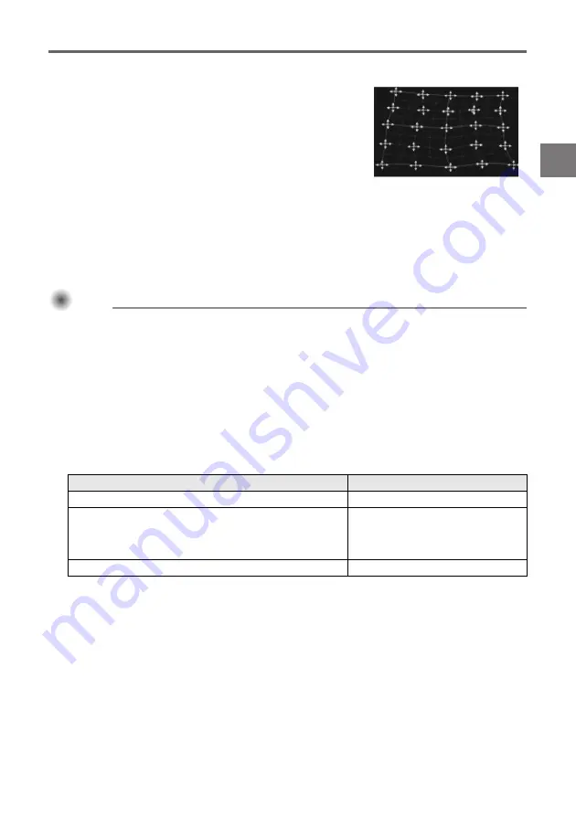
4-Point Correction is the same as Corner Correction. 
It is recommended that you first perform 4-Point Correction to align 
the four corners of the projected image with the target screen, and 
then perform the other types of correction in ascending order 
(9-Point, 25-Point, 81-Point) to fine tune the correction. (The nearby 
screenshot shows the screen when 25-Point Correction is selected.)

To perform this type of clear operation:

Select this menu item:

Correction of point specified in step 1

Current point

All point corrections made using the correction type 
specified by the menu item, as well as all point corrections 
made using more detailed correction types

*

4-Point Correction, 
9-Point Correction, 
25-Point Correction, 
81-Point Correction

*

All point corrections, regardless of correction type

All points

Summary of Contents for YA-S10

Page 1: ...ottenere la versione più aggiornata di questo manuale visitare il sito web all URL riportato di seguito http world casio com manual projector Installationshandbok Svenska Förvara all användardokumentation nära till hands för framtida referens Den senaste versionen av detta instruktionshäfte kan hämtas från webbplatsen med följande URL adress http world casio com manual projector Guia de Configuraç...

Page 2: ...ntions The term Projector System in this manual refers to the systems below z XJ SK600 Dual Projection System z XJ SK650 Dual Projection System z The projector systems made up of the YA S10 Geometric Correction Box connected to one or two separately available CASIO projectors NOTE z Some models covered by this manual may not be available in certain geographic areas User Documentation This manual e...

Page 3: ...irety is forbidden You are allowed to use this manual for your own personal use Any other use is forbidden without the permission of CASIO COMPUTER CO LTD z CASIO COMPUTER CO LTD shall not be held liable for any lost profits or claims from third parties arising out of the use of this product or this manual z CASIO COMPUTER CO LTD shall not be held liable for any loss or lost profits due to loss of...

Page 4: ... injury and against material damage The meaning of each of the symbols is explained below Icon Examples Danger This symbol indicates information that if ignored or applied incorrectly creates the risk of death or serious personal injury Warning This symbol indicates information that if ignored or applied incorrectly could possibly create the risk of death or serious personal injury Caution This sy...

Page 5: ...ic shock Make sure that you always observe the following precautions Never place heavy objects on the power cord and never expose it to heat Make sure the power cord is not pinched between the wall and the rack or table where the Projector System is located and never cover the power cord with a cushion or other object Never try to modify the power cord allow it to become damaged or subject it to e...

Page 6: ...ectric shock Immediately perform the following steps Disposal by burning Never try to dispose of the Projector System by burning it Doing so can cause an explosion which creates the risk of fire and personal injury Location Never locate the Projector System in any of the following types of locations Doing so creates the risk of fire and electric shock Near an area subject to strong vibration An ar...

Page 7: ... the Projector System from the power outlet if you do not plan to use it for a long time At least once a year unplug the power plug and use a dry cloth or vacuum cleaner to clear dust from the area around the prongs of the power plug Never use detergent to clean the power cord especially the power plug and jack Before moving the Projector System be sure to turn it off and unplug it from the power ...

Page 8: ... disposing of any of the part or the entire Projector System be sure to do so in accordance with the laws rules and regulations in your geographic area Danger Should liquid leaking from an alkaline battery get into the eyes immediately take the following steps 1 Do not rub the eyes Wash the eyes with clean water 2 Contact a physician immediately Failure to take immediate action can lead to loss of...

Page 9: ... System is installed or any of the components of the Projector System to impact while projection is being performed Doing so can cause projection to be momentarily interrupted followed by discoloration of the image and error generation If the screen becomes discolored use the Control Box remote controller s INPUT key to re select the input source you want to project This should return the image to...

Page 10: ...t while the System is running z Use under high ambient temperature or in environments subjected to large amounts of dust oil smoke tobacco smoke or other types of smoke can shorten the replacement cycles of the optical engine and other components Using the Projector System in such an environment will require more frequent replacement of such components which you will be charged for For details abo...

Page 11: ...he YA S10 Control Box provides full simultaneous control of both of them Operations for two projectors are virtually the same as controlling a single projector z Wired LAN and RS 232C Control Support Some Control Box functions can be controlled from an external device Crestron controller computer etc NOTE z If you have an XJ SK600 or XJ SK650 Projector System refer to the Unpacking section in the ...

Page 12: ...commended z For information about supported projectors visit the CASIO website Make sure you correctly install the projector s to be connected to the Control Box referring to the applicable user documentation Important Important Important z After you set up the Control Box projector s and projection screen secure all of these components to ensure that they will not move during use If the position ...

Page 13: ...er and the input source device Wiring 1 To control the Projector System from an external device over a LAN use a commercially available LAN cable to connect this terminal to the LAN terminal of the external device 2 To control the Projector System from an external device over an RS 232C connection use a commercially available serial cable cross to connect this port to the serial port of the extern...

Page 14: ...u have two projectors connected to the Control Box you will need to perform the procedure below on both of them To configuring the initial settings of the projector s 1 Remove the Projector lens cover 2 Turn on Projector 3 After projection starts perform the required operation on the projector to focus the projected image z For information about how to focus see the User s Guide that comes with th...

Page 15: ...nus are displayed in English 3 Select Option Settings and then Language and then use the U and I keys to select the language you want 4 Configure the settings below as required For details about each setting refer to the YA S10 User s Guide z Option Settings 3 Eco Mode z Image Properties 3 Color Mode z Option Settings 3 Remote Power Numbers 5 Next perform the procedure under Adjusting the Position...

Page 16: ...djustment 1 Perform rough position alignment 2 Attach the lens cover to the lens of Projector B only so only the Projector A image is being projected on the projection screen 3 Adjust the position and size of the Projector A image so it slightly runs off the edges of the target screen 4 Remove the lens cover from the lens of Projector B so its image is projected 5 Adjust the position and size of t...

Page 17: ...izontal no left right sloping z Adjust so the vertical lines of the crosshairs in the center of the adjustment pattern are in the center of the screen 10 On the remote controller press the BLANK key z This will cause the Projector B adjustment pattern to disappear leaving only the Projector A adjustment pattern yellow 11 While observing the Projector A adjustment pattern perform the vertical adjus...

Page 18: ...trol Box settings page E 14 turn on Control Box power 2 Adjust the position and size of the projector image so it slightly runs off the edges of the target screen 3 On the remote controller press the CORRECT key 4 On the Image Shaping menu that appears select Adjust Image Position and then press the ENTER key z This should display an adjustment pattern z Adjust the focus of the pattern as required...

Page 19: ... You can select one of the shaping methods described below Changing the Projected Image View while Shaping an Image IMAGE Key While you are performing image shaping on a projected image you can use the IMAGE key to toggle the projected image between the grid and the input source image Shaping the Image to Match the Projection Screen Flat This shaping type is mainly for correcting for keystoning th...

Page 20: ... power If an image is being projected press the CORRECT key to display the Image Shaping menu 2 Select a Shaping Type setting in accordance with the type of surface you are projecting to z Under initial Default Box settings Flat is selected for Shaping Type Important Important Important z The steps in the example used for this procedure assume a standard flat screen projection surface target scree...

Page 21: ... This will cause the shaping cursors to start flashing which indicates that shifting of the cursors to a different location is enabled 4 Use the X key to move the flashing shaping cursor to the upper right corner of the Projector A image and then press the CORRECT key z This will stop the cursor flashing which indicates that you are now able to move the upper right corner of the grid 5 Use the S T...

Page 22: ...and be replaced by yellow Projector A image shaping cursors 10 Repeat steps 2 through 9 toggling the movement speed between slow and fast with the CORRECT key as many times as required to fine tune the adjustment Adjust the Projector A and Projector B images until they satisfy the conditions below z The four corners of the two grids align as precisely as possible with the four corners of the targe...

Page 23: ... Default Control Box settings Flat is selected for Shaping Type Important Important Important z The steps in the example used for this procedure assume a standard flat screen projection surface target screen with Flat selected for Shaping Type For information about how to deal with other shaped projection surfaces refer to Using Shaping Functions page E 24 3 Perform corner correction z The four co...

Page 24: ...ight corner of the projector image and then press the CORRECT key z This will stop the cursor flashing which indicates that you are now able to move the upper right corner of the grid 5 Use the S T W and X keys to move the upper right corner of the grid so it is aligned with the upper right corner of the target screen 6 Repeat steps 3 through 5 above to align the lower right and lower left corners...

Page 25: ...tion using Shaping Type Flat 1 Press the CORRECT key to display the Image Shaping menu 2 Select Shaping Type and then press the ENTER key 3 Select Flat and then press ENTER z If there are previous corrections made with a different shaping type a dialog box with the message All image shaping will be cleared Do you want to continue will appear To clear the current shaping and change the shaping type...

Page 26: ...ping type a dialog box with the message All image shaping will be cleared Do you want to continue will appear Select Yes and then press ENTER 4 Use the Image Shaping menu to select one of the following shaping types in accordance with the target screen to be projected upon Corner Correction Base And Side Adjustment Side Correction Arch Center Point Correction z For details about what you can do wi...

Page 27: ... to continue will appear Select Yes and then press ENTER 4 On the Image Shaping menu select Point Correction and then press the ENTER key 5 On the Point Correction submenu that appears select 4 Point Correction and then press the ENTER key z This will display a grid for 4 point correction 6 Perform 4 point correction z For details see Point Correction on page E 29 z A method is available to clear ...

Page 28: ... and X keys to move the cursor After moving the shaping cursor to the desired location press the CORRECT key Toggle between the Projector A image and Projector B image Press the A B key Hide the grid of the image of the projector that is not selected Press the BLANK key Display the Image Shaping menu Press the ESC key Use it for this To reduce keystoning that occurs when the screen is at an angle ...

Page 29: ...djustment affects the bases while horizontal adjustment affects the sides When Cylinder 2 is selected as the shaping type vertical adjustment affects the sides while horizontal adjustment affects the bases The nearby screenshot shows the screen when Cylinder 1 is selected How it works The four positions of the projected image described below can be manipulated Cylinder 1 vertical cylinder z Upper ...

Page 30: ... Correction then 25 Point Correction would appear Selecting 25 Point Correction in this case would clear all corrections made using 25 Point Correction as well all corrections made using 81 Point Correction 5 Press the ENTER key to execute the clear operation z This will exit the menu and return to the grid display Use it for this To reduce projected image distortion that occurs when projecting in...

Page 31: ...ss the ENTER key z This should display a circular adjustment pattern If the adjustment pattern does not appear as a circle if it looks more like a vertical or horizontal oval perform the steps below to adjust it If the adjustment pattern does appear as a circle press the ESC twice to exit the adjustment procedure 3 On the menu select Applicable Screen and then use the W and X keys to cycle the set...

Page 32: ...he numbered power key 1 through 4 assigned to the Control Box you want to turn on For more information see To configure initial Control Box settings page E 14 and Control Box Power On Off page E 14 To change the input source When both HDMI input and RGB or component input sources are connected to the Control Box you can use the remote controller INPUT key to toggle between them Follow the instruct...

Page 33: ...mately 0 67kg 1 5lbs GPL and LGPL 1 This product uses software This Software that comes under the GNU General Public License GPL and GNU Lesser General Public License LGPL In accordance with the GPL and LGPL the source code of This Software is open source code Anyone who wishes to view the open source code can do so by downloading it from the CASIO Projector download site Whenever copying modifyin...

Page 34: ...crease the separation between the equipment and receiver z Connect the equipment into an outlet on a circuit different from that to which the receiver is connected z Consult the dealer or an experienced radio TV technician for help FCC WARNING Changes or modifications not expressly approved by the party responsible for compliance could void the user s authority to operate the equipment Proper conn...

Page 35: ...ASIO COMPUTER CO LTD 6 2 Hon machi 1 chome Shibuya ku Tokyo 151 8543 Japan Responsible within the European Union CASIO EUROPE GmbH Casio Platz 1 22848 Norderstedt Germany Batterij niet weggooien maar inlevern als KCA ...

Page 36: ...Printed in China Imprimé en Chine MA1301 A RJA528056 001 ...

Reviews: