background image

V-R200 Installation Manual

– 4 –

II.  Installing the Product

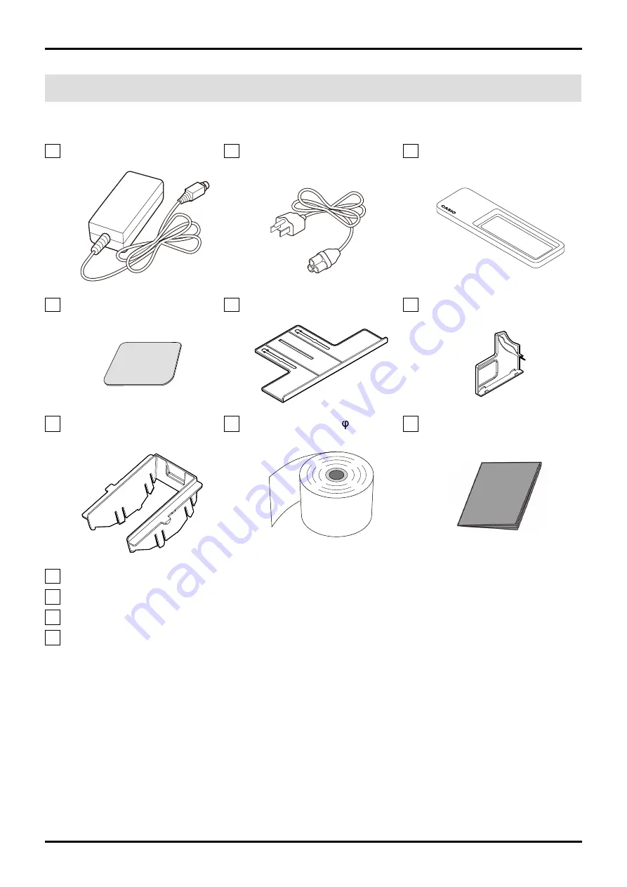
1.  Checking the accessories

AC adaptor

Power cord (US only)

Multi-purpose tray

Magnetic plate

Pop tray

Tilt switch cover

Spacer

Paper roll of 80 mm ( 30)

Dust cover

(For paper roll of 58 mm)

Connector cover fastening screw

User's Manual

Warranty (US only)

WEEE Caution sheet (EU only)

Summary of Contents for V-R200

Page 1: ...V R200 Installation Manual Ver 1 00E ...

Page 2: ... R200 how to connect optional parts how to turn the power or shut down V R200 etc Please read this Installation Manual before you install V R200 For the items not described in this Installation Manual please refer to the following manual Y V R200 User s Manual The manual is included in the product V R200 Name of parts specifications etc are described in this manual ...

Page 3: ...g an SD SDHC memory card P 6 5 Setting the paper roll P 8 6 Adjusting the angle of the main display P 10 7 Configuring the printer settings P 11 III Installing Options 1 MCR P 12 2 DRAWER P 16 3 Multi purpose tray P 19 IV Information 1 Basic Operation 1 General information P 20 2 Shutdown procedure P 21 2 SD SDHC memory card 1 Recommended SD SDHC memory card P 22 2 Mounting the SD SDHC memory card...

Page 4: ...posed to hot air This may result in fire Use only the designated power supply for the AC adaptor and fully insert the power plug of the AC adaptor into the outlet Select the outlet where the power cord of this product is easily reached and plug unplug of the power plug can easily be performed Do not pinch the power cord between objects such as products walls and shelves Also do not put heavy objec...

Page 5: ...rability of the product secure installation space as shown below Do not place any objects within the installation space indicated by the dotted rectangle within 50 mm from the product 50 mm 50 mm 50 mm 50 mm Fig 2 3 Dimensions of the product 395 mm 237 mm 229 mm Fig 3 ...

Page 6: ...BK 186 W 121 D 170 H mm with extension pole kit A VA B70DE VA B73PK BK 186 W 121 D 350 H mm with extension pole kit B VA B70DE VA B73LPK BK 186 W 121 D 500 H mm Customer display serial cable QT 6061CB B Length 0 4 m QT 6062CB B Length 5 0 m VA B63CB Length 1 5 m Magnetic card reader VA A46MCR 128 W 42 D 64 H mm Cash Drawers M sized DL 2814 400 W 398 D 113 H mm DL 2815 DL 2822 DL 2823 DL 2436 Cash ...

Page 7: ...ng the accessories AC adaptor Power cord US only Multi purpose tray Magnetic plate Pop tray Tilt switch cover Spacer Paper roll of 80 mm 30 Dust cover For paper roll of 58 mm Connector cover fastening screw User s Manual Warranty US only WEEE Caution sheet EU only ...

Page 8: ...or cover Fig 4 2 Connect necessary cables DC jack USB port LAN port COM3 port COM2 port COM1 port Fig 5 3 Run the cables from the side of the product as shown in Fig 6 and attach the connector cover by fastening the included connector cover fastening screw Connector cover fastening screw Fig 6 ...

Page 9: ...de mechanism Fig 7 Stopper Round holes Pop tray 2 Slide the pop tray in the direction of the arrow and pull it out to the position to be used Fig 8 Do not use the pop tray so as to protrude from the surface where the product is installed Doing so may result in damage 4 Inserting an SD SDHC memory card 1 Put your finger into the slot on the side and remove the side cover Fig 9 Slot Side cover ...

Page 10: ...D SDHC memory card into the memory card slot with its surface facing the display of the product Fig 11 4 Secure the card cover with the screw and then attach the side cover Fig 12 The SD SDHC memory card is automatically mounted when it is inserted If it has been unmounted due to incorrect operation select Settings Storage Mount SD card ...

Page 11: ...n the printer cover Fig 13 2 Push the paper holder lever toward you in the direction of the arrow until it makes a clicking sound Fig 14 Paper holder lever 3 While pushing the paper holder lever toward you lift it up and open the paper holder to the position where it stops naturally Fig 15 ...

Page 12: ...setting the print width refer to 7 Configuring the printer settings P 11 4 Hold the end of paper roll so it comes out from below and load it in the paper compartment Fig 17 5 Snap the paper holder against the paper roll until both ends lock by pushing down on the middle area with the PUSH HERE sticker Fig 18 Pressing only one side of the paper holder will only lock one side causing printing errors...

Page 13: ...daptor to the outlet and turn the power switch ON Fig 19 Power switch 2 Adjust the angle of the main display to a position that suits the operator s work by pressing the tilt switch Fig 20 TILT DOWN UP TILT DOWN UP 3 Attach the tilt switch cover to secure the angle of the main display Fig 21 ...

Page 14: ... default factory setting is 80 mm NOTE When printing with the print width set to 58 mm do not change the print width to 80 mm Doing so may result in printing errors 1 From the menu select Settings Device administration Device settings Fig 22 2 Set the Print Width When the value is changed Test Print changes to Apply Fig 23 Fig 24 3 Select Apply OK appears for a few seconds and then disappears Fig ...

Page 15: ...ackage MCR unit Protective plate Screws Binding head screw x 2 Countersunk head screw x 2 2 Peel off the tape from the MCR unit Fig 26 Tape 3 Peel off the tape from the bottom of the product 4 Undo one binding head screw shown in Fig 27 NOTE The screw is used for installing the MCR unit Fig 27 Tape Binding head screw ...

Page 16: ...e the countersunk head screws included in the MCR NOTE If the screws are fully tightened the projection of the protective plate cannot be inserted into the MCR unit in the later procedure Fig 28 Countersunk head screws Fig 29 Protective plate 6 Connect the connector of the MCR unit to the product Fig 30 ...

Page 17: ...slide the protective plate to insert its projection into the MCR unit See Fig 32 Fig 31 Fig 32 NOTE Be sure that the protector black seal plastic plate of the MCR cable fits inside the protective plate NOTE Be sure that the MCR cable is not caught Fig 33 Mounting reference video of the protective plate Playback Left click on the image with a blue frame or left click on where the cursor appears End...

Page 18: ...tive plate with three binding head screws NOTE Pay attention to the screw length The included two screws are a little shorter than the one that was removed in Step 4 9 Be sure that the MCR cable is not caught Then fully tighten the two countersunk head screws Fig 34 Countersunk head screws Binding head screws included Binding head screw ...

Page 19: ...wer fixing hook 1 Drawer fixing sheet 1 1 The drawer fixing hook is for M size drawer only 2 Connect the drawer connecting cable to the drawer Fig 35 NOTE Connect the longer side drawer connecting cable Cable length About 85 cm NOTE For the drawer with an earth terminal connect the earth terminal of the drawer connecting cable ...

Page 20: ...ault it can be opened by moving the drawer release lever tab on the drawer bottom Fig 36 Drawer release lever The drawer will not open if it has been locked with the drawer lock key Unlock the lock Fig 37 Drawer lock key If the drawer tilts forward when the drawer is opened Normal Tilting forward Fig 38 Fig 39 ...

Page 21: ...drawer fixing sheet and attach the drawer fixing sheet to the drawer fixing hook Fig 40 Fig 41 2 Peel off the other side of release paper from the drawer fixing sheet Fig 42 3 Attach the drawer fixing hook to the surface where the drawer is installed and slide the drawer toward the drawer fixing hook to fix it Fig 43 Fig 44 Fig 45 1 2 ...

Page 22: ... Multi purpose tray Use the multi purpose tray as a container for small items by putting it on the drawer Since the tray has magnets on the bottom it is attracted to the VR 200 s genuine drawer Front Rear Fig 46 Fig 47 Magnets Fig 48 ...

Page 23: ...ssed The reset switch is pressed Reboot without shutdown The power switch is held down more than 5 sec then choose Power off The maintenance switch is held down more than 5 sec OFF state Power lamp OFF ON state Power lamp Green Sleep state Power lamp Orange NOTE Power lamp Red Insufficient capacity of the internal memory backup battery Do not shutdown the power supplied to the product or unplug th...

Page 24: ...ays to shut down Shutting down by the power switch Press and hold the power switch until Power off force tablet reboot appears Select Power off OK Fig 51 Fig 52 Shutting down by the maintenance switch Press and hold the maintenance switch until Pwer off appears Fig 53 ...

Page 25: ...DSDB 016 SDSDUL 016 TS16GSDU1 Fig 54 2 Mounting the SD SDHC memory card SD SDHC memory card is automatically mounted when it is inserted If it has been unmounted due to incorrect operation mount it again Select Settings Storage Mount SD card Fig 55 3 Unmounting the SD SDHC memory card Select Settings Storage Unmount SD card OK Fig 56 ...

Page 26: ...tic plate is used to temporarily keep paper money received from the customer Front Rear Protective tape Release paper Fig 57 Clean the surface where the magnetic plate is to be attached Then attach the magnetic plate taking care to avoid injury Fig 58 Fig 59 ...

Page 27: ...CASIO COMPUTER CO LTD Overseas CS Department TOKYO JAPAN 2016 CASIO COMPUTER CO LTD ...

Reviews: