— 6 —
Pulse B
Pulse A
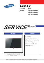
Color Adjustment
* Open soldering pad IF.
Input
Input
Input
Output
Output
Connection Point
Signal
Connection
Point
Adjust
Result
Pattern
generator
Signal
generator
Color bar
45.75 MHz
70 dB
µ
TP2
VR311
Oscilloscope
TP5
Signal
generator
Pattern
generator
Oscilloscope
Input
TP2
Output
TP5
Adjust VR311 so that the
difference
between pulse
A and B is less
than 0.1V.
Pulse B
Pulse A
Tint Adjustment
* Open soldering pad IF.
AGC Adjustment
Pattern
generator
TV Signal
generator
TP7
VR204
IF levelmeter
TP2
Pattern
generator
Signal
generator
Color bar
45.75 MHz
70 dB
µ
TP2
VR325
Oscilloscope
TP5
Adjust VR325 so that the
difference
between pulse
A and B is less
than 0.1V.
Signal
generator
Pattern
generator
IF levelmeter
Input
TP7
Output
TP2
Signal
generator
Pattern
generator
Oscilloscope
Input
TP2
Output
TP5
Color bar
65
±
5 dB
µ
Adjust for 84
±
1 dB
µ
reading on the IF levelmeter
TV-5100
Set
TV-5100
Set
TV-5100
Set