background image

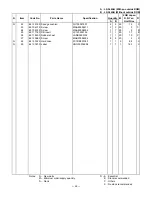
A : LX-546AQ (With an outside ROM)
B : LX-546AR (Without outside ROM)

 FOB Japan

N

Item

Code No.

Parts Name

M    N.R.Yen

R

A

B

  Unit Price

N

22

6413 3180 Sponge cushion

FH100027507

2

2

20

15

X

23

6510 4310 Screw

MAA80006311

2

2

20

3

C

24

6510 4350 Screw

MAA80006302

1

1

20

2

B

25

6511 7160 RB insert

LC120000102

1

1

20

17

B

26

6511 8400 Rubber sheet

LADB0220105

1

1

20

10

C

27

6512 0980 Screw

MAB20086306

8

8

20

2

X

N

28

6413 3220 Hard case

FC1DB201023

1

1

5

88

X

N

29

6413 3230 Label

HGG00014908

1

1

1

120

X

   Notes:     N –  New parts

R – A : Essential

M –  Minimum order/supply quantity

B : Stock recommended

R –  Rank

C : Others

X : No stock recommended

Quantity

Specification

— 26 —

Summary of Contents for SF-4300R

Page 1: ...R with price SF 4300R LX 546 OCT 1994 SF 4300R ...

Page 2: ...SET OPERATION 10 5 2 TO ADJUST THE DISPLAY CONTRAST 11 5 3 TO CHECK THE MEMORY STATUS 11 5 4 THE SOUND MENU 11 6 LSI IC Pin function 12 6 1 CPU 12 6 2 RAM MB84256A 70 10LL LSI3 ROM µPD23C1001EAGW K81 LSI4 13 6 3 VOLTAGE REGULATOR S 81253SGUP REG1 14 6 4 VOLTAGE DETECTOR S 80752AN DET1 14 7 TROUBLESHOOTING 15 8 HARD CHECK 18 9 ASSEMBLY VIEW 23 10 PARTS LIST 25 ...

Page 3: ... 1 1 SCHEMATIC DIAGRAM 1 1 MAIN PCB ...

Page 4: ... 2 1 2 KEY MATRIX ...

Page 5: ...ry life Approximately 400 hours continuous operation in Telephone Directory Approximately 350 hours repeating one minute of input and 10 minutes of display in Telephone Directory Approximately 12 months for memory back up Auto power off Approximately 6 minutes after last key operation Operating temperature 0 C 40 C 32 F 104 F Dimensions Unfolded 9 6H 122W 158 5Dmm 3 8 H 4 3 4 W 6 1 4 D Folded 12 4...

Page 6: ...ied alarm time set Approximately 1020 under the following conditions 1 item per day 20 characters per item 30 days per month Starting time specified no alarm time Reminder Approximately 1680 under the following conditions 10 characters per item Alarm time set Approximately 1900 under the following conditions 10 characters per item No alarm time ...

Page 7: ... battery with a new one making sure that the positive side of the new battery is facing up so you can see it 4 Replace the battery holder and secure it by tightening its screw Be careful that you do not over tighten the screw 5 Repeat steps 2 through 4 for another battery Be sure to replace all two batteries Never mix old batteries with new ones and be sure to use CR2032 lithium batteries only 6 A...

Page 8: ...slave machine 4 DATA TRANSFER SF 4300R can transfer customers data to other SF 4300R with memory protection only when replacing the LCD or the outer case How to transfer the data Before connecting the cable SB 60 62 be sure to reset the slave machine to clear all data 1 Turn off the power switch and connect the two units using the cable SB 60 62 as shown in the drawing M SUN 1901 2 3 SB 60 62 acce...

Page 9: ... the two SF Units using the optional SB 60 62 cable You can also connect them using an SB 60 62 cable Important Be sure to replace the connector covers on the SF Units when you are not performing data communications 4 Check the hardware parameters 1 Select TEL mode or press 1 under MENU screen 2 Press FUNC twice to display the second function menu You can perform the above operation while the init...

Page 10: ...ation while the initial screen of the Memo Mode Schedule Keeper Calendar or Reminder is displayed also 2 Press 4 to select DATA COMM 3 Press 2 to select RECEIVE 6 Set up the customer s machine 1 While an initial screen is displayed press FUNC twice to display the second function menu You can perform the above operation while the initial screen of the Memo Mode Schedule Keeper Calendar or Reminder ...

Page 11: ...dar To abort the send operation at any time press ESC If an error occurs during the send operation the message TRANSMIT ERROR appears on the display Press ESC to clear the error message 6 After the send operation is complete the display returns to the initial screen of the mode you were in when you started this procedure 1 ONE ITEM 2 MODE DATA 3 ALL DATA SEND SEND ALL DATA SET ESC 4 3 1 SEND 2 REC...

Page 12: ... SF Unit s memory Make sure that you really want to delete the data before you continue 2 Press Y to reset the memory and delete all data or N to abort the reset operation without deleting anything Note that the letter key you press to indicate yes depends on the system language as noted below Czech A English Y Spanish S Hungarian I Polish T Portuguese S Russian Y Following the reset operation des...

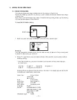
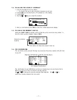
Page 13: ...any mode except the Calculator mode here 2 Press SHIFT and confirm that the S indicator is on the display 3 Press CONT 4 Use the and keys to adjust the contrast 5 After you are finished press ESC to clear the contrast adjustment display 5 3 TO CHECK THE MEMORY STATUS Hold down SHIFT CAPA to display a screen that shows the current memory status To clear the memory status display release CAPA CAPACI...

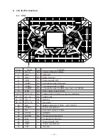
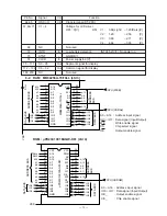
Page 14: ...3 WEB Out Write enable signal for RAM 14 15 RA15 16 Out Address bus for ROM only used in LX 546AQ 16 30 A0 14 Out Address bus 31 38 IO0 7 I O Data bus 39 54 KY0 15 I O Key signal 55 SW In Battery switch On L 0 V Off H 6 V 56 DEBUG Test for manufacturer 57 ON Out Data communication enable 58 CRCKI In GND 0 V 59 SOUTB Out Transmission data output 60 SIN In Transmission data input 61 VDD In Power sup...

Page 15: ...tput WE Write enable signal CS Chip select signal OE Output enable signal ROM µPD23C1001EAGW K81 LSI 4 A14 A12 A7 A6 A5 A4 A3 A2 A1 A0 IO0 IO1 IO2 GND VCC WE A13 A8 A9 A11 OE A10 CS IO7 IO6 IO5 IO4 IO3 28 27 26 25 24 23 22 21 20 19 18 17 16 15 1 2 3 4 5 6 7 8 9 10 11 12 13 A14 A12 A7 A6 A5 A4 A3 A2 A1 A0 A13 A8 A9 A11 A10 IO7 IO6 IO5 IO4 IO3 IO0 IO1 IO2 VSS CPU CSRA2 DATA BUS ADDRESS BUS DATA BUS ...

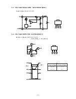
Page 16: ...ut 5 3V 5 6 4 VOLTAGE DETECTOR S 80752AN DET1 Detection Voltage VDET 5 2V 2 5 5 07 V MIN 5 33 V MAX Input voltage Output voltage 5 2 V 5 V 5 2 V 0 V 2 Vin 1 Vout 3 GND 1 GND 2 Vin 3 Vout OUT GND VIN VREF RA RB 1 2 3 RI 1 2 3 VDD OUT VSS VSS VDD VDD VDD VDET VDET ...

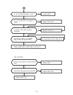
Page 17: ...t with the battery springs Adjust contrast Replace batteries Check other function Refer to No Erratic display Adjust contact and clean battery spring N Y Y N N Y Y N N Is contrast adjustment OK Is power of batteries enough Y Is 3 pin of S 81253 REG1 5 3 V N N Are capacitor C8 C9 C10 C11 C12 OK Y Replace REGT1 1 Replace C8 C9 C10 C11 C12 Y ...

Page 18: ... Y N Resolder RAM LSI3 or ROM LSI4 Replace RAM LSI3 or ROM LSI4 or CPU LSI1 Does key make positive contact with PCB Ass y N Y Resolder CPU LSI1 Is 1 Pin of S 80752AN DET 1 5 V Is 11 Pin of CPU LSI 1 sending the signal 1 Does RAM or ROM for LX 546AQ make positive contact with PCB DoesCPUmakepositivecontactwithPCB Y Replace CPU LSI1 ...

Page 19: ...LSI1 make positive con tact with PCB CONTRAST MAX Resolder Y N Resolder Replace CPU IC Y High current consumption Y Check PCB Is there any short circuit Y N Are the several capacitors OK Replace capacitors Are voltage of several capacitors enough V1 1 3 V V2 2 5 V V3 2 7 V V4 3 9 V Replace CPU LSI1 Check solder part of C6 C7 C8 C9 C10 or replace ...

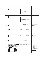
Page 20: ...display Checker display Reverse checker display 1 2 3 5 6 7 TEST 2 MEMORY MENU 3 KEY 4 BUZZER 1 DISP 5 I F DISP 4 RVS 1 WHITE 5 FRAME 2 BLACK 6 DOT 4 3 CHECK 7 TIME Main menu Display check 1 4 2 3 4 SELF TEST PROG PRESS SEARCH QUIT BY OFF CASIO AUG 1993 The short pad is located behind the tape I 1 SEARCH ...

Page 21: ...ME Check if timer is working Key check 9 8 10 11 12 No display 13 Dots appear at 4 corners TIME DISPLAY 00 00 00 14 Check the key No appears on the display Check the key sounds To return to the menu mode enter SEARCH 00 01 02 03 04 56 57 KEY 1 RANDOM 2 AUTO TEST 2 MEMORY MENU 3 KEY 4 BUZZER 1 DISP 5 EXT 3 7 ESC 6 5 2 ...

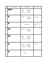
Page 22: ... 1 sound 15 16 17 18 19 20 21 Buzzer check SEARCH TEST 2 MEMORY MENU 3 KEY 4 BUZZER 1 DISP 5 EXT BUZZER 1 BEEP 2 ALARM1 3 ALARM2 4 2 ESC BUZZER 1 BEEP 2 ALARM1 3 ALARM2 TEST 2 MEMORY MENU 3 KEY 4 BUZZER 1 DISP 5 EXT ESC 2 MEMORY 3 WR2 4 READ2 1 WR1 5 DUMP 2 READ1 6 CHKSUM 1 ...

Page 23: ...f RAM has defect error message will be appered MEMORY 3 WR2 4 READ2 1 WR1 5 DUMP 2 READ1 6 CHKSUM 25 ESC 26 5 00001 00002 00004 00008 00010 00020 00040 00080 00100 00200 00400 00800 01000 02000 04000 08000 10000 The address of ROM LSI4 should be appeared Only for LX 546AQ TEST 2 MEMORY MENU 3 KEY 4 BUZZER 1 DISP 5 EXT ESC Press RESET key 28 27 ESC ...

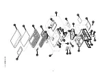
Page 24: ...9 ASSEMBLY VIEW 23 28 29 21 20 22 2 1 5 18 4 c9 c11 LSI JC1 X1 25 6 10 27 12 7 26 9 11 14 13 24 15 19 23 8 27 17 16 3 ...

Page 25: ... 0 2 20 6 C N R5 6512 1380 Chip resistor CC1801D11E7 1 1 20 3 C N R6 6512 1410 Chip resistor CC0473D11T3 1 1 20 3 C R7 6510 4770 Chip resistor CC1001311C0 1 1 20 5 C N R8 9 6512 1360 Chip resistor CC0012D11T6 2 2 20 3 C REG1 2105 3290 Regulator S 81253SGUP DIJ T1 1 1 5 60 B X1 6510 4550 Crystal BD0063P2509 1 1 5 55 B 1 3335 4606 LCD CD418 TS 1 1 1 350 A 2 6409 6270 Hot melt film FX200P40056 1 1 5 ...

Page 26: ...24 6510 4350 Screw MAA80006302 1 1 20 2 B 25 6511 7160 RB insert LC120000102 1 1 20 17 B 26 6511 8400 Rubber sheet LADB0220105 1 1 20 10 C 27 6512 0980 Screw MAB20086306 8 8 20 2 X N 28 6413 3220 Hard case FC1DB201023 1 1 5 88 X N 29 6413 3230 Label HGG00014908 1 1 1 120 X Notes N New parts R A Essential M Minimum order supply quantity B Stock recommended R Rank C Others X No stock recommended Qua...

Page 27: ...MA0100451A ...

Reviews:

Related manuals for SF-4300R