background image

E-45

Important!

Allowing the power supply terminals become wet can cause an electric shock 
or 

fi

 re.  In addition, if the terminals become soiled, contact may be impaired 

resulting in poor charging.  For reasons of safety and maintaining charging 
battery pack(s) in optimum condition, clean the power supply terminals by 
wiping with a dry cloth or cotton swab after disconnecting the AC adaptor.
Never short out the power supply terminals of the USB Cradle.  This can 
damage the USB Cradle.
Note that subjecting the Cradle to impacts or strong vibration could dislodge the 
Handheld Terminal. Also avoid any vibration or impacts during communication 
with a USB client or USB host as this can cause communication to be 
interrupted.
When mounting the DT-X200, securely attach to the mount hooks of the USB 
Cradle and make sure that the power LED at the front of the USB Cradle is lit in 
green. Charging and communication will not proceed properly if the DT-X200 is 
not mounted properly.
Always cap ports that are not being used. Using the USB Cradle while the ports 
are uncapped can cause damage.
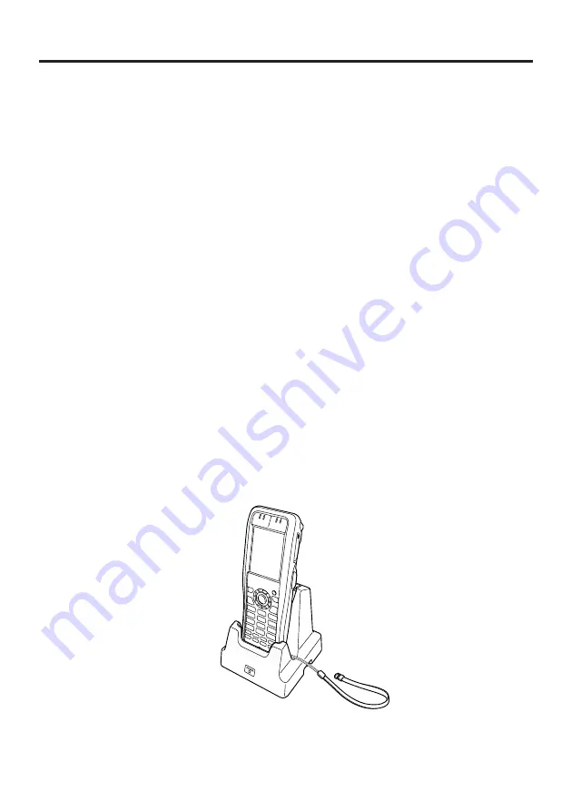
If the hand strap is attached to the terminal, take care not to trap it when 
mounting the DT-X200. Pull the hand strap out as shown in the illustration. If 
you are having dif

fi

 culties mounting the DT-X200, attach the hand strap using 

the strap hole on the top of the terminal. 
Place the Cradle on a 

fl

 at, level surface and take care when placing the DT-X200 

in or removing it from the cradle.

Summary of Contents for DT-X200 Series

Page 1: ...Handheld Terminal User s Guide Series Be sure to read Safety Precautions inside this guide before trying to use your Handheld Terminal E DT X200 ...

Page 2: ...lied warranties of merchantability or fitness for any particular purpose BLUETOOTH is a registered trademark owned by Bluetooth SIG Inc and licensed to CASIO COMPUTER CO LTD Microsoft and Windows are either registered trademarks or trademarks of Microsoft Corporation in the United States and or other countries FeliCa is a contactless IC card technology developed by SONY Corporation and a registere...

Page 3: ... attach the hand strap E 20 Calibrating Touch Panel Alignment E 21 Setting the Display Brightness E 22 Adjusting Display Brightness E 22 Display Auto Dimmer E 22 Using the Laser Scanner Laser Models E 23 Bar Code Scanning Position E 24 Adjusting the Laser Light Emission Width E 25 Using the CMOS Imager Imager Models E 27 Using the Full Range Imager Full Range Imager Models E 28 Handling the NFC Re...

Page 4: ...dle Power Supply E 49 Specifications E 52 Using the Cradle type Dual Battery Charger HA K36DCHG E 53 General Guide E 53 Charging Battery Pack E 55 Connecting Multiple Cradle type Dual Battery Charger E 58 Specifications E 59 Using the USB and Charging Unit HA K65US E 60 General Guide E 60 Mounting the USB and Charging Unit E 61 Removing the USB and Charging Unit E 62 Connecting to a Computer E 62 ...

Page 5: ...u should not do The symbol shown here indicates you should not try to take the unit apart A black circle indicates something you should do The symbol shown here indicates you should unplug the unit from the wall outlet Warning Disassembly and Modification Never try to disassemble or modify the Handheld Terminal and its options including battery pack and battery in any way Abnormal Conditions Shoul...

Page 6: ...RF exposure compliance requirements a separation distance of at least 2 9cm in wireless operation must be maintained between the terminal and all persons around This terminal must not be co located or operating in conjunction with other transmitter Caution Foreign Objects Take care to ensure that metals or combustible objects are not inserted into the openings of the Handheld Terminal or its optio...

Page 7: ...hit it with a hammer or step on it Use only the specified battery charger to charge the battery pack Warning Never place the battery pack in a microwave oven or any other high voltage device If the amount of time period the battery pack can serve becomes considerably short even after it has been fully charged for the specified time period stop using it Should the battery pack start to leak or emit...

Page 8: ...p between the prongs of the plug Dust built up between the prongs can lead to the danger of fire Check that the connector is properly oriented and then push it straight in do not insert upside down Do not allow fluids or foreign objects to get into the AC adaptor Choose a location where the power cord is readily accessible and can be easily plugged in and unplugged When using the AC adaptor always...

Page 9: ...d scratch the display The power supply terminals and Data Communication terminals should be cleaned from time to time using an implement such as a dry cotton bud Soiling on the terminals may cause connection defects Take care when using chemicals Applying thinners gasoline kerosene solvents or oils or substances such as cleaners adhesives paints medications or toiletries that contain those materia...

Page 10: ...ack in a temperature outside of the recommended range causes deterioration When used at low temperatures the battery pack has a reduced capacity and will supply power for shorter time The life span of the battery pack is also shortened Charging the battery pack while the battery pack itself is freeze including inside causes deterioration Be sure to resume an ordinary room temperature on the batter...

Page 11: ... the battery pack cover microSD card slot cover or on the respective contact surfaces If any soiling is found wipe it off with a clean soft dry cloth Even very small amounts of soiling trapped on the contact surfaces a single hair or grain of sand etc can cause water to leak into the device Check that the waterproof seals on the battery pack cover and microSD card slot cover are free from cracks a...

Page 12: ...s a warning and caution label for Class 2 laser products that comply with IEC60825 1 2007 Although Class 2 laser light is only emitted momentarily never look directly into the beam light The laser light emitted by this laser scanner has a maximum output of less than 1 mW and a wavelength of 650 nm Use of controls or adjustments or performance of procedures other than those specified herein may res...

Page 13: ...ut the problem Regulatory Information Europe Manufacturer CASIO COMPUTER CO LTD 6 2 Hon machi 1 chome Shibuya ku Tokyo 151 8543 Japan Responsible within the European Union Casio Europe GmbH Casio Platz 1 22848 Norderstedt Germany www casio europe com DT X200 Options of DT X200 Please keep all information for future reference The declaration of conformity may be consulted at http doc casio com Prod...

Page 14: ... and Charging Unit HA K65US Cradle type Battery Charger HA K36DCHGE Dual Battery Charger HA F32DCHG USB Cable Cradle computer connection DT 380USB A AC Adaptor for Ethernet Cradle Dual Battery Charger AD S42120C AC Adaptor for USB Cradle USB and Charging Unit AD S15050B AC Adaptor for Cradle type Dual Battery Charger AD S90190C Battery Pack HA K23XLBAT Power Cord AC CORD AC CORD2 Hand Belt HA K95H...

Page 15: ...E 13 General Guide 13 1 2 3 4 5 6 8 7 9 10 15 14 11 12 17 18 20 16 28 19 20 16 22 22 16 16 23 27 24 25 24 25 26 21 Left Front Right Top Bottom Back The illustration shows DT X200 10E 11E 20E 21E ...

Page 16: ...on and off 8 R Key Can be assigned an arbitrary function 9 L Key Can be assigned an arbitrary function 10 Enter Key Press when finishing entering numerical values or when moving to the next step 11 Numeric Keys Used to enter numeric values and decimal points 12 Function Keys F1 Similar function as the Alt key on a PC keyboard F2 Similar function as the Shift Tab keys combination on a PC keyboard U...

Page 17: ... using NFC hold the card or tag up to the reader 22 Hand Belt Mount Used to attach the hand belt 23 Extension Port Provided for future extension 24 Battery Pack Cover Lock Switches Used to lock the battery cover and to release 25 Mount Holes These holes hold the terminal seating in the optional USB Cradle or in the Ethernet Cradle 26 Battery Pack Cover Used to cover the battery compartment that ho...

Page 18: ...e battery pack powers normal operation and also provides power required to maintain memory contents while the backup battery provides backup power to maintain memory contents Because of this you should not remove the battery pack if the backup battery is dead Removing the battery pack while the backup battery is dead causes data in the memory to be corrupted or lost Note that once data is lost it ...

Page 19: ... pack HA K23XLBAT Take care that the battery pack is oriented correctly when you load it In addition load the battery pack while making sure that the end of the battery pack removal tape is protruding above the battery pack 3 Put back the battery pack cover in the compartment as instructed by the arrows and in the illustration and then turn the lock switches to the LOCK position ...

Page 20: ...mory to be deleted When removing the battery pack be sure you carefully follow the proper procedure as explained in this guide Never try to use other type of battery than the ones that are specified for this product When removing the battery pack pull the removal tape straight up and remove the battery pack Removing with excessive force can damage the battery pack Before starting to use the Handhe...

Page 21: ...terminal near the top use the hole that affords the greatest ease of use Attach the pen cord according to the procedure described below 1 Pass the loop on the end of the pen cord the end not attached to the pen through the cord hole on the back of the terminal near the top 2 Then pass the pen through the loop Important Do not swing the Handheld Terminal around holding the pen cord ...

Page 22: ...the greatest ease of use Attach the hand strap according to the procedure described below To attach the hand strap 1 Pass the thin cord of the hand strap through the strap hole on the back of the Handheld Terminal 2 Pass the other end of the strap the part you put around your wrist through the loop formed by the thin cord Important Do not swing the Handheld Terminal around holding the hand strap ...

Page 23: ...Fn key and then press the 4 key after confirming that F is displayed in the lower right corner of the screen The following screen is displayed You can also display this screen by navigating as follows Start Settings Stylus Screen Align Screen Press the stylus against the center of the target mark mark as indicated on the screen Press the stylus against the target mark on the screen 5 times to disp...

Page 24: ...splay while pressing the 6 key adjusts brightness for a lighter display In order to continue to make adjustments press the 5 key or 6 key again after first pressing the Fn key You can set the brightness by tapping Brightness in the Control Panel Display Auto Dimmer The display auto dimmer automatically lowers display brightness if you do not perform any operation for a specific period of time This...

Page 25: ...ompleted normally Indicator 2 displays a green light Important If you are unable to scan a bar code try changing the angle at which the scanner is held or distance from the scanner to the bar code and then try scanning again This Handheld Terminal is capable of scanning bar codes at a distance of about 40 550 mm Furthermore the distance at which scanning is possible may vary according to the bar c...

Page 26: ...tance from the bar code so that the bars enter the light when scanning large bar codes Margin Margin Good Good Good Bad Bad Bad Bad Warning Never look directly into the laser light The products with the integrated Laser Scanner module scan bar codes using laser light Never look directly into the laser light or shine the laser light into the eyes ...

Page 27: ...nt can be adjusted Adjust the emission width when it is improper 1 Navigate to the menus in the following sequence Start Settings Control Panel The Control Panel appears as shown in the screen 2 Double tap the Scanner Setting icon The Setting screen appears as shown in the screen 3 Tap the Others tab in the Scanner Setting screen ...

Page 28: ...to emit laser light and align the light with the barcode for adjusting emission width Align the laser light with the narrow bars on both sides The message appears as shown at right when adjustment is completed Repeat the setting if Setting failed message appears Emission Width Adjustment Bar code ...

Page 29: ...ther bar codes nearby When reading a bar code in large size adjust the position of the Handheld Terminal so that the entire code is enclosed within the laser frame For small size move the Handheld Terminal closer to it Important If you have problem not properly reading a code change the angle and or the distance between the code and the Handheld Terminal and try reading it again A bar code can be ...

Page 30: ...ar care aligning the light when there are other bar codes nearby When reading a bar code in large size adjust the position of the Handheld Terminal so that the entire code is at proper distance For small size move the Handheld Terminal closer to it Important If you have problem not properly reading a code change the angle and or the distance between the code and the Handheld Terminal and try readi...

Page 31: ... can be used to read RFID tags used for controlling goods as well as contactless IC cards used in applications such as employee identification RFID Tags 1 Hold the Handheld Terminal up so that the reader port is parallel with the RFID tag Contactless IC Cards 1 Hold the contactless IC card up so that it is parallel with the Handheld Terminal s reader port Otherwise you can hold the Handheld Termin...

Page 32: ...not to strike the reader port against the card or tag If the card or tag cannot be read try moving the Handheld Terminal back and forth or side to side Contactless IC cards Metal objects near a contactless IC card will interfere with successful reading Take the card out of a wallet if the wallet is with metal object before applying it to the reader port The card may not be read correctly if it is ...

Page 33: ...described below Installing 1 Open the cover of the microSD card slot and insert a microSD card all the way in until the top of the microSD card aligns with the entrance of the slot of the Handheld Terminal Insert the card firmly all the way into the slot Avoid inserting the card diagonally 2 Close the cover of the microSD card slot ...

Page 34: ...A microSD card must be inserted with the top and bottom properly aligned and in the proper direction Attempt in inserting it with an excessive force in incorrect orientation can risk damage to the connectors and slot Never turn off the power or remove a microSD card from the slot while the card is being accessed Doing so can damage the microSD card or data in the card Do not drop the card or lose ...

Page 35: ...eing turned on communication may be interrupted or TV and radio receptions may be interfered images on the screen produced by certain channels of UHF and broadcast satellite may become blurry Normal communication may not be possible in an area near a broadcast trans mitter or wireless transmitter If this happens move the Handheld Terminal to a different location Normal communication may not be pos...

Page 36: ... Performing a Full Reset Initialization Performing a full reset deletes all data and resets various settings to their defaults Data stored in the Flashdisk folder remain unaffected Perform a full reset whenever any one of the following conditions exists When you want to delete installed programs and settings and resume the terminal to the initial condition When you are no longer able to use the Ha...

Page 37: ...operation press the L Trigger key R Trigger Key 2 Press the R Trigger key This causes the message shown below to appear To cancel the full reset operation press the L Trigger key R Trigger Key 3 Press the R Trigger key again to perform the full reset The full reset starts and all data in the memory are erased and the start up screen appears Data stored in the Flashdisk folder remain unaffected ...

Page 38: ...directional RSS 14 GS1 DataBar Limited RSS Limited GS1 DataBar Expanded RSS Expanded Code32 GS1 DataBar Truncated RSS 14 Truncated ISBT Stacked 2D PDF417 Micro PDF Composite Codablock F GS1 DataBar Stacked Omnidirectional RSS 14 Stacked GS1 DataBar Expanded Stacked RSS Expanded Stacked GS1 DataBar Stacked RSS 14 Stacked Matrix 2D Aztec DataMatrix Maxicode QR Code Micro QR Chinese Sensible Code Han...

Page 39: ...m touching the case ISO15693 0 mm touching the case Communication Area Area in 32 mm 20 mm card tag dependent Supported Cards ISO14443TypeA ISO14443TypeB FeliCa JIS X 6319 ISO15693 microSD Memory Card Slot Compatible with SDHC Memory Card Power Requirements Power Source Battery Pack HA K23XLBAT Memory Backup Rechargeable Lithium Battery Built in Consumption Current DC 2 2A DT X200 10E 11E DC 2 4A ...

Page 40: ...E 38 Weight DT X200 10E 11E Approximately 290g when battery pack is installed DT X200 20E 21E 41E Approximately 295g when battery pack is installed ...

Page 41: ...5 8 Display Approx 32mm 1 1 4 Display Approx 41mm 1 5 8 Approx 57mm 2 1 4 Grip Approx 187mm 7 3 8 Approx 35mm 1 3 8 Grip DT X200 10E 11E 20E 21E Approx 32mm 1 1 4 Display Approx 44mm 1 3 4 Approx 187mm 7 3 8 Approx 35mm 1 3 8 Grip DT X200 41E ...

Page 42: ...to the ditch Make sure that the metal part is firmly seated 2 Thread one end of the hand belt through the hand belt hook Then fold it back and set the belt in proper length by adjusting the hook loop fastener Removing the hand belt 1 As shown in the figure pull out the metal part of the hook while pressing down the protrude part that has a small dimple on it 2 Loose the hook loop fastener and then...

Page 43: ...s it possible to transmit system data and file data between the Handheld Terminal and a PC via a USB connection download or upload You can also use the USB Cradle to charge the battery pack installed in the Handheld Terminal General Guide 4 5 Top 6 7 Front 3 Right 2 1 Back ...

Page 44: ...h Turns the power on and off 4 Power Supply Data Communication Terminals Power is supplied to the DT X200 via these contacts Also used for data communication 5 Terminal Detect Switch This switch detects when the DT X200 is seated correctly on the Cradle 6 Mount Hooks These hooks are used to stabilize the Handheld Terminal when mounting it on the cradle 7 Power Indicator LED This LED indicates the ...

Page 45: ...mmunication with the Handheld Terminal Power to the Handheld Terminal is supplied from the USB Cradle 1 Plug the AC adaptor into the AC adaptor jack on the back of the USB Cradle 2 After connecting the power cable to the AC adaptor plug the other end of it into an electrical outlet 3 Connect the USB cable DT 380USB A to the USB client port on the back of the USB Cradle and then connect it to the P...

Page 46: ...at indicator 1 on the DT X200 lights To remove the DT X200 from the USB Cradle tilt the DT X200 forward to disengage the mount hooks from the mount holes and then lift the DT X200 out of the cradle Status of Indicator 1 on DT X200 Orange Charging the battery pack Red Flashing Standby due to battery pack error or the surrounding temperature is out of the charging temperature range charging begins w...

Page 47: ...ation with a USB client or USB host as this can cause communication to be interrupted When mounting the DT X200 securely attach to the mount hooks of the USB Cradle and make sure that the power LED at the front of the USB Cradle is lit in green Charging and communication will not proceed properly if the DT X200 is not mounted properly Always cap ports that are not being used Using the USB Cradle w...

Page 48: ...e AC adaptor AD S15050B Consumption Current 5V DC approximately 3 0A Output to Handheld Terminal 5V DC 3 0A max 4 AC Adaptor Model AD S15050B Input 100V to 240V AC 50 60Hz 0 36 0 2A Output 5V DC 3 0A 5 Dimensions and Weight Dimensions Approximately 110 W 111 D 126 H mm Weight Approximately 307g 6 Operating Environment Temperature 0 C to 40 C 32 F to 104 F Humidity 10 to 90 RH non condensation ...

Page 49: ...ble to transmit system data and file data between the Handheld Terminal and a PC via a USB or LAN connection download or upload You can also use the Ethernet Cradle to charge the battery pack installed in the Handheld Terminal General Guide 11 12 Front 9 10 Top 8 Left 7 Right 6 5 4 3 2 1 Back ...

Page 50: ... cradle to a PC or hub via a LAN cable so that system data and file data can be transmitted uploaded or downloaded The special driver software must be installed in the DT X200 6 AC Adaptor Jack Connect the AC adaptor sold separately here 7 Power Switch Turns the power on and off 8 Selector Switch This switch is used to switch between a USB connection and a LAN connection LAN LAN A USB host B USB c...

Page 51: ... the Ethernet Cradle 1 Plug the AC adaptor into the AC adaptor jack on the back of the Ethernet Cradle 2 After connecting the power cable to the AC adaptor plug the other end of it into an electrical outlet 3 Use the selector switch on the left side of the Ethernet Cradle to select the port to be used Set the switch to the LAN position when using the LAN port on the cradle Set the switch to the B ...

Page 52: ...ide of the Ethernet Cradle The power LED on the front of the Ethernet Cradle lights red 6 Align the terminals on the bottom of the DT X200 with the power supply terminals in the Ethernet Cradle before inserting the DT X200 Push the DT X200 fully into the Ethernet Cradle until the mount hooks in the cradle engage the mount holes in the DT X200 Check that the power LED on the front of the Ethernet C...

Page 53: ...n swab after disconnecting the AC adaptor Never short out the power supply terminals of the Ethernet Cradle This can damage the Ethernet Cradle Note that subjecting the Cradle to impacts or strong vibration could dislodge the Handheld Terminal Also avoid any vibration or impacts during communication with a LAN USB client or USB host as this can cause communication to be interrupted When mounting t...

Page 54: ...Charge Period Approximately 4 hours 4 Power Supply Power Source AC adaptor AD S42120C Consumption Current 12V DC approximately 2 0A Output to Handheld Terminal 5V DC 3 0A max USB Host Output 5V DC 0 5A max 5 AC Adaptor Model AD S42120C Input 100V to 240V AC 50 60Hz Output 12V DC 3 5A 6 Dimensions and Weight Dimensions Approximately 110 W 111 D 126 H mm Weight Approximately 325g 7 Operating Environ...

Page 55: ...ery Charger HA K36DCHGE can concurrently charge two battery packs installed in the respective DT X200s General Guide Side Upper 4 3 1 Bottom 4 2 5 6 7 Bundled Items Use these bundled items to join multiple chargers together Bottom bracket Side bracket Screws for brackets Two each for one bracket ...

Page 56: ... attaches here when you connect multiple Cradle type Dual Battery Chargers to each other 5 Power Contacts Power is supplied to the DT X200 via these contacts 6 Mount Hooks These hooks are used to stabilize the Handheld Terminal when mounting it on the Cradle type Dual Battery Charger 7 Power LEDs These LEDs indicate the power status and the mounting status of the DT X200 Off Power off Green Power ...

Page 57: ...r jack on the dual battery charger with the engraved side of the connector facing upwards Push the connector firmly into the jack until it clicks into place 2 After connecting the power cable to the AC adaptor plug the other end of it into an AC outlet 3 Turn on the power switch on the side of the charger The power LEDs on the top of the charger light red ...

Page 58: ...he charger The power LEDs on the top of the charger light green and indicator 1 lights orange Indicator 1 Status of Indicator 1 on DT X200 Orange Charging the battery pack Red Flashing Standby due to battery pack error or the surrounding temperature is out of the charging temperature range charging begins when the temperature is within the charging temperature range Green Charging the battery pack...

Page 59: ...00 before placing it in the charger If the Indicator 1 on DT X200 starts blinking unplug the AC adaptor from the AC outlet and then plug in it back When placing the DT X200 into the charger take care not to trap the pen cord or hand strap in the charger Pull the hand strap out as shown in the illustration If you are having difficulties mounting the DT X200 attach the hand strap using the strap hol...

Page 60: ... covers of the Cradle type Dual Battery Chargers you want to connect to each other Connector covers 2 Connect the two Cradle type Dual Battery Chargers as shown below Connectors 3 Fix the side and bottom brackets in place with two screws on each bracket You can repeat the above steps to connect up to 3 Cradle type Dual Battery Chargers Attach the connection brackets so that the front side faces ou...

Page 61: ... be left over Keep these as spare for use in future Always disconnect the AC adaptor before joining multiple chargers together Specifications Charge period Approximately 4 hours Power source AD S90190C Rated input DC19V 4 74A Operating temperature 0 C to 40 C 32 F to 104 F Operating humidity 30 to 80 RH Dimensions Approximately 159 W 100 D 85 H mm 61 4 W 315 16 D 33 8 H Weight Approximately 495g 1...

Page 62: ...neral Guide 2 1 Bottom 3 Top 4 Left 4 Right 1 AC Adaptor Jack This port is used to transmit system data and file data download upload by connecting the USB and Charging Unit to a PC using a USB cable DT 380USB A A dedicated driver must be installed in the PC before connecting the USB and Charging Unit to the PC 2 USB Client Port Connect the AC adaptor sold separately here 3 Power Supply Data Commu...

Page 63: ...other liquids on the power supply data communication terminals on the USB and Charging Unit or terminal can lead to an electric shock or fire Note also that soiling on the terminals will impair the connection leading to reduced charging functionality As a safety precaution disconnect the AC adaptor and USB cable before cleaning the power supply terminals with a dry cloth or cotton bud If there is ...

Page 64: ...he USB and Charging Unit by pressing them inwards as shown in the illustration 2 Keeping the stoppers pressed in pull the USB and Charging Unit off the terminal Connecting to a Computer Connect to a computer using the USB and Charging Unit with the USB cable DT 380USB A PC USB cable DT 380USB A ...

Page 65: ...S15050B An indicator on the DT X200 shows the level of charge AC Adaptor AD S15050B Status of Indicator 1 on DT X200 Orange Charging Red Flashing Standby due to battery pack error or the surrounding temperature is out of the charging temperature range charging begins when the temperature is within the charging temperature range Green Charging complete ...

Page 66: ... AD S15050B Consumption Current 5V DC approximately 3 0A Output to Handheld Terminal 5V DC 3 0A max AC Adaptor Model AD S15050B Input 100V to 240V AC 50 60Hz 0 36 to 0 2A Output 5V DC 3 0A Dimensions and Weight Dimensions Approximately 64 W 45 D 66 H mm 21 2 W 13 4 D 25 8 H Weight Approximately 57g 2oz Operating Environment Temperature 0 C to 40 C 32 F to 104 F Humidity 10 to 90 RH non condensatio...

Page 67: ...Battery Charger HA F32DCHG can be used to simultaneously charge two battery packs General Guide 3 Left 1 Top Right 2 3 Bottom 4 5 Front 1 Charge Indicator LED 2 AC Adaptor Jack 3 Dual Battery Charger Connection Port 4 Connection Bracket Attachment Holes 5 Power Supply Terminals ...

Page 68: ...ed correctly insert it into the Dual Battery Charger This causes the Charge Indicator LED to light in red indicating that charging has started Status of Charge Indicator LED Off Not charging the battery pack Red Charging the battery pack Red Flashing Battery pack problem Green Charging the battery pack is complete Green Flashing Standby due to the surrounding temperature being beyond the specified...

Page 69: ...AC adaptor 1 As shown in the illustrations below remove the connector covers of the Dual Battery Chargers you want to connect to each other Connector cover 2 Connect the two Dual Battery Chargers as shown below 3 Turn over the connected Dual Battery Chargers and attach a connection bracket securing it in place with screws You can repeat the above steps to connect up to 3 Dual Battery Chargers ...

Page 70: ...ture 2 Power Supply Power Source AC adaptor AD S42120C Consumption Current 12V DC 3 5A Output 4 2V DC 1 1A max 3 AC Adaptor Model AD S42120C Input 100V to 240V AC 50 60Hz 1 2A Output 12V DC 3 5A 4 Dimensions and Weight Dimensions Approximately 108 W 104 D 45 H mm 41 4 W 41 8 D 13 4 H Weight Approximately 152g 5 4oz 5 Operating Environment Temperature Approximately 0 C to 40 C 32 F to 104 F Humidit...

Page 71: ... discharge or chemical decomposition by the battery pack itself If the battery pack fails to hold its operating duration after it has been fully charged replace it with a new one The battery pack may reach the end of its service life Battery Pack Specifications Model HA K23XLBAT Rated Capacity 2860mAh 6 84 Wh Rated Voltage 3 7V Dimensions Approximately 36 15 W 55 40 D 18 10 H mm 17 16 W 23 16 D 11...

Page 72: ...CASIO COMPUTER CO LTD 6 2 Hon machi 1 chome Shibuya ku Tokyo 151 8543 Japan ...

Reviews: