Casio DT-930M50E User Manual Download Page 40

Using the Bar Code Reader

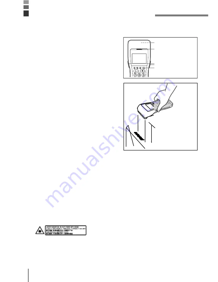
Performing a Bar Code Read Operation

1

press the trigger key.

Trigger key
Power key

2

code. The read indicator lights green when
the read is successful.

Maximum distance:
Approx. 45 cm
(forward-facing
reader port model)
and approx. 40 cm
(down-facing reader
port model)

Important!

the label and Handheld Terminal or move closer and then try again.

· If the bar code is wider than the width of the Handheld Terminal’s reader

port, try moving the Handheld Terminal a bit farther away from the bar
code.

· The Handheld Terminal should be able to read a bar code from the

maximum distance of 45 centimeters on the forward-facing reader port
model and about 40 centimeters on the down-facing reader port model
under the following conditions.

Ambient Light: 500~900 lux (fluorescent)

PCS: 0.9 min.
Minimum Bar Width: 1.0 mm CODE-39
ITF (extended version)

· Wavelength: 650 nm

Maximum output: 1.0 mW

· CAUTION

EXPLANATORY LABEL

may result in hazardous radiation exposure.

E-28

Summary of Contents for DT-930M50E

Page 1: ...casio 400 1166 021 Handheld Terminal Series User s Guide Data Collection Terminal...

Page 2: ...Be sure to read Safety Precautions inside this guide before trying to use your Handheld Terminal After reading this guide keep it in a safe place for future reference PN430041 001...

Page 3: ...BLUETOOTH is a registered trademark owned by Bluetooth SIG Inc and licensed to CASIO COMPUTER CO LTD E 2...

Page 4: ...to become familiar with these markings and symbols so you can avoid future problems Danger personal injury This symbol indicates information that if ignored or Warning serious personal injury This sym...

Page 5: ...come connected shorted by metal Doing so creates the danger of battery pack heat emission explosion and fire Never transport or store the battery pack together with a necklace hair pins or other metal...

Page 6: ...E 4...

Page 7: ...bjects Should any foreign matter ever get into the unit immediately turn off the power and contact your original dealer or an authorized CASIO service provider Continued use creates the danger of fire...

Page 8: ...hysician immediately If the alkali fluid gets in your mouth rinse your mouth with water and contact a physician immediately If the alkali fluid gets on your skin or clothes it may burn your skin thoro...

Page 9: ...E 6...

Page 10: ...minals with tape to insulate them Mixing them with other batteries or metal objects may cause the coin type lithium battery to short leak fluid overheat explode or burst into flames Lithium ion Batter...

Page 11: ...chargers creates the danger of fire and electrical shock Should the power cord ever become severely damaged to the point that wires are exposed or broken contact your original dealer or CASIO service...

Page 12: ...f heat emission and fire as well as deterioration of battery pack performance and shortening of its service life Do not use the battery pack in areas where static electricity is being generated Doing...

Page 13: ...o not store the batteries in the direct sunlight or in a car on a sunny day when it is very hot The batteries may leak fluid overheat or explode When storing or disposing of the batteries cover the te...

Page 14: ...E 10...

Page 15: ...Be sure to turn the power OFF and unplug the power cord after use Unplug the power cord from the wall outlet and clean the area around the plugs at least once a year If dust collects on the AC adapto...

Page 16: ...Terminal Do not wipe with a wet cloth Do not use benzine thinner or other volatile chemicals which can result in deformation and deterioration of the materials used in the keys and case Do not lay the...

Page 17: ...E 12...

Page 18: ...suites so that they effectively use the frequency spectrum allocated to terrestrial space radio communication and orbital resources so to as to avoid harmful interference as included in following stan...

Page 19: ...E 13...

Page 20: ...does not cover programming and the uploading of data See the separate manuals for details of these procedures Contents Safety Precautions E 3 Introduction E 12 Handling Precautions E 12 Unpacking E 1...

Page 21: ...IR Communication E 32 Bluetooth Communication E 33 Specifications E 34 Lithium Ion Battery Pack DT 923LIB E 35 Using the Bridge Basic Cradle E 36 Setting up the Bridge Basic Cradle E 37 Connecting wi...

Page 22: ...tions E 47 Using the Satellite Cradle E 48 General Guide E 48 When You Are Using the Down facing Reader Port Model E 50 Setting up the Satellite Cradle E 50 Charging the Battery Pack E 53 Charging the...

Page 23: ...tery Charger E 60 Charging the Battery Pack charging the lithium ion battery pack separately E 63 DT 969CHGE Cradle type Battery Charger Specifications E 65 Installing Cradles and Cradle type Battery...

Page 24: ...User s Guide B e sure t o r ead Sa fety P recautions insid e t his guide b efore tryi ng t o your H andheldTerm inal After r eading this g uide keep i t i n a safe p lace futur e r eference P Desktop...

Page 25: ...Available Models and Options Options Bridge Basic Cradle HA E60IO DT 930 M50E DT 930 M51E E 17...

Page 26: ...AC adaptor for Cradle type Battery Charger DT 9020 ADP GS DT 9020ADP US RS 232Ccable DT 782RSC Male RS 232Ccable DT 783RSC female RS 232Ccable DT 787AX female RS 232Ccable DT 881RSC connection RS 232C...

Page 27: ...General Guide Left side 1 2 3 4 5 12 7 7 14 1 2 read red when the read is no good 3 4 5 other operations 6 located inside the hole 7...

Page 28: ...n 10 Back up battery compartment 11 Main battery compartment 12 Main battery compartment lock Locks the main battery compartment cover in place Handheld Terminal power is automatically cut if the cove...

Page 29: ...OFF Use only two AA LR6 size alkaline batteries or the dedicated lithium ion battery pack The lithium ion battery pack discharges naturally during its transportation from the factory to an end user Be...

Page 30: ...replace it with a new one The battery pack may reach the end of its E 20...

Page 31: ...rect directions Loading the alkaline batteries 1 lock to the FREE position and remove the cover 2 into the main battery compartment making sure that they face the directions shown in the figure 3 Hand...

Page 32: ...Remove the alkaline batteries following the loading procedure in reverse Be sure to turn the Handheld Terminal OFF before you do this E 21...

Page 33: ...oad the battery while sliding it in with the mark on the lithium ion battery pack aligned with the mark in the main battery compartment 3 Handheld Terminal and slide the main battery compartment cover...

Page 34: ...do this Caution For Important Data When you remove the backup battery with the main battery removed or in a low power state data may be lost or may change Data cannot be recovered once it is lost or c...

Page 35: ...ith a dry cloth before inserting it with the plus side up as shown in the diagram 4 by the arrow to hook it 5 the screws Removing the battery 1 ballpoint pen or other sharp object to remove the backup...

Page 36: ...2 the screws E 24...

Page 37: ...d ANK 21 columns x 10 lines 16 columns x 8 lines 12 columns x 6 lines ANK 21 columns x 5 lines 16 columns x 4 lines 12 columns x 3 lines Character Types Alphanumeric symbols Text Effects Bolding highl...

Page 38: ...ing damaged as a result of it being dropped by mistake during movement Follow the procedure below to attach the wrist strap To attach the wrist strap 1 the metal hand strap mount two possible location...

Page 39: ...d Their Functions Keys available on the Handheld Terminal and their functions are as follows 1 2 1 2 3 Keys that can be assigned any function 4 the Handheld Terminal is in the character input 6 7 5 6...

Page 40: ...wider than the width of the Handheld Terminal s reader port try moving the Handheld Terminal a bit farther away from the bar code The Handheld Terminal should be able to read a bar code from the maxim...

Page 41: ...ween the Handheld Terminal and the bar code For larger bar codes position the Handheld Terminal so that the bar code fits into the laser beam Warning Laser Beam Never look directly into the laser beam...

Page 42: ...beam s reference point beforehand 1 and system menu 2 Mode Set Bar Code Laser Beam Adjustment TRG START CLR EXIT 3 adjustment bar code Align the laser beam with the fine bars on both sides of the adju...

Page 43: ...eed not be adjusted Adjustment is necessary only when the laser beam does not switch to the correct position when the beam width is switched Adjustment results are stored in memory Factory settings ar...

Page 44: ...ing the infrared ports on the bottom of the units Position the two DT 930 units so they will not accidently move during communication The orientation of the two units depends on the type of communicat...

Page 45: ...approaching such a device when its power is turned on proper communication may prove impossible while this may also cause interference with TV and radio reception images produced by certain UHF and b...

Page 46: ...rox 400 mm max DT 930M50E Input Stroke Keys Infrared Communications Interface Conforms to IrDA Ver 1 1 original Control Protocol Half duplex Synchronization Asynchronous frame synchronization Speed 2...

Page 47: ...ackup Battery life backup power Dimensions and Weight Dimensions Approx 69 4 W x 173 D x 31 6 H display Don t include protrusions Approx 57 4 W x 173 D x 21 9 H grip Don t include protrusions DT 930M5...

Page 48: ...Weight E 35...

Page 49: ...dle Top P O W E R 35 4 Front POWER 1 1 is mounted Off Lit Green Power is ON and the DT 930 is correctly mounted Lit Red Power is ON and the DT 930 is not correctly mounted 2 Off Lit Green USB connecti...

Page 50: ...power 8 and file data Also to draw power through the connection to the PC A special driver needs to be installed in the PC before connecting the Handheld Terminal to the PC 9 10 Desktop unit when moun...

Page 51: ...sic Cradle 2 before connecting the power cord to the electrical outlet 3 USB port on the back of the Bridge Basic Cradle and then connect it to the personal computer 4 the DT 930 and the infrared inte...

Page 52: ...E 37...

Page 53: ...Important on the front of the Bridge Basic Cradle lights green If it is not correctly mounted communication cannot be done Do not allow the supply contacts in the Bridge Basic Cradle to short circuit...

Page 54: ...unit to remove it Screws 2 screws for the wall mount unit Screws 3 where the hole on the top of the wall mount unit is to be fixed Do not screw the screw all the way in Leave about 2 mm between the wa...

Page 55: ...E 39...

Page 56: ...Setting up the Bridge Basic Cradle 4 through the hole on its top POWE R 5 the lower hole of the wall mount unit POWE R 6 Removing the Wall Mount Unit 1 2...

Page 57: ...ant Cradle to the wall E 40...

Page 58: ...Power supply Power Source USB bus power Rated input When using USB bus power 0 4 A max 4 AC adaptor Model no Input Output 5 Dimensions and Weight Dimensions Desktop Wall mount Weight Desktop Wall mou...

Page 59: ...les DT 788RSC to connect up to 16 Basic Cradles Use the RS 232C cable DT 782RSC DT 783RSC DT 787AX for connecting the Cradle to a personal computer The Basic Cradle can be located on a desk or table t...

Page 60: ...Power indicator Indicate whether power is ON or OFF and if the Handheld Terminal is mounted Off Power OFF Lit Red Power ON Handheld Terminal not mounted Lit Green Power ON Handheld Terminal mounted 8...

Page 61: ...Use these holes to attach the Basic Cradle to a hook on a wall E 43...

Page 62: ...aptor for Basic Cradle to connect to an electrical outlet Be sure to connect the AC adaptor and then turn on the power on the Basic Cradle before performing any communication with the Handheld Termina...

Page 63: ...of the Basic Cradle 5 After making sure that the power of the Basic Cradle and personal computer is OFF remove the cover and connect one end of the optional RS 232C cable DT 782RSC DT 783RSC DT 787AX...

Page 64: ...inal to the Basic Cradle making sure their infrared ports come into close contact with each other The color of the Basic Cradle power supply indicator changes to green when proper connection is achiev...

Page 65: ...one L for left or R for right marking is imprinted on the back of each desktop guide and wall mount guide both accompanied with DT 930 Be sure to install the new guides properly on the Basic Cradle th...

Page 66: ...puter Connections First connect Basic Cradle RS 485 1 and then the RS 485 2 of the Basic Cradle that you want to connect to DIP Switch Settings Cable DT 788RSC The following table shows the various se...

Page 67: ...wer Supply Power Source AC adaptor DT 9020ADP GS or DT 9020ADP US Power Requirements AC 230 V DT 9020ADP GS AC 120 V DT 9020ADP US Rated Input DC 9 5 V approx 1 000 mA Functions Infrared interface RS...

Page 68: ...r the lithium ion battery pack Use the RS 232C cable DT 881RSC DT 882RSC DT 883RSC DT 887AX AXA for connecting the Satellite Cradle to a personal computer The Satellite Cradle can be located on a desk...

Page 69: ...eld Terminal is mounted onto the Satellite Cradle Off All Handheld Terminals mounted on the Satellite Cradle are unable to communicate or there is a system problem Lit Green Normal system operation On...

Page 70: ...rminal mounted 11 Desktop guides L R Holds down the Handheld Terminal on the Satellite Cradle that is placed on a flat surface in desktop configuration 12 Charge Power supply terminals Supplies power...

Page 71: ...17 DIP swi tch es Use these switches to set the operational configuration of the Satellite Cradle 18 Wal l mou nti ng hol es Use these holes to attach the Satellite Cradle to a hook on a wall E 49...

Page 72: ...adaptor for Satellite Cradle to connect to an electrical outlet Be sure to connect the AC adaptor and turn on Satellite Cradle power before performing any communication with the Handheld Terminal Pow...

Page 73: ...dle is in the OFF position plug the other end of the AC adaptor into the AC terminal at the top of the Satellite Cradle 5 After making sure that the power of the Satellite Cradle and personal computer...

Page 74: ...The power Infrared port indicator on the Satellite Cradle lights red 7 Attach the Handheld Terminal to the communication port making sure that the infrared ports on its base come into close contact w...

Page 75: ...Power switch ON when system operation is normal and the e communication with another Handheld Terminal connected to a Satellite Cradle...

Page 76: ...System operation indicator Communication indicator Spare battery pack charge indicator CHG 2 Battery pack charge indicator n starts...

Page 77: ...CHG 1 Power indicator E 51...

Page 78: ...n the back of each desktop guide and wall mount guide both accompanied with DT 930 Be sure to install the new guides properly on the Satellite Cradle the desktop guides for desktop configuration or th...

Page 79: ...E 52...

Page 80: ...e Battery Pack Temperature ranges for battery pack use in the Handheld Terminal charging and storage are specified below Temperatures outside these ranges create the danger of deterioration of battery...

Page 81: ...med simultaneously while charging of the battery in the Handheld Terminal Caution Ambient Temperature Ranges for the Battery Pack Temperature ranges for battery pack use in the Handheld Terminal charg...

Page 82: ...figuration This configuration makes it possible to exchange data between multiple Handheld Terminals and a personal computer via the cradles Connections Connect C OUT on the Satellite Cradle nearest t...

Page 83: ...ontrol 9 Off 1 2 3 4 5 6 7 8 9 10 Use Special Software ON Satellite Cradle Host Computer Communication speed 6 2 400bps 4 800bps 9 600bps 19 200bps 38 400bps 57 600bps 115 200bps Communication speed c...

Page 84: ...on Speed Charger Charge Method Charge Time Power Supply Power Source AC adaptor AD S42120AE Power Requirements AC100 to 240V Rated Input DC 12 V approx 3 500 mA during charging Functions Infrared inte...

Page 85: ...the Handheld Terminal and a spare battery pack DT 923LIB installed in the spare battery compartment on the charger The Cradle type Battery Charger can be located on a desk or table top or mounted on...

Page 86: ...harging Lit Green Charging complete 5 Battery pack charge indicator Indicates the charge status of the lithium ion battery pack in the CHG 1 Handheld Terminal Off Not charging e g lithium ion battery...

Page 87: ...e battery pack separately 10 Pow er swi tch Turns power ON and OFF 11 Bas e Reverses the position of the base when wall mounting the Cradle type Battery Charger 12 Wal l mou nti ng hol es Use these ho...

Page 88: ...e type Battery Charger Use only the AC adaptor specified for use with the Handheld Terminal to connect to an electrical outlet Be sure to connect the AC adaptor and turn Handheld Terminal power on bef...

Page 89: ...Battery Charger The power indicator on the Cradle type Battery Charger lights red Power switch OFF 6 Attach the Handheld Terminal to the Cradle type Battery Charger making sure the charge terminals on...

Page 90: ...Power switch ON Lit Red Charging Lit Green Charge complete OFF No battery pack Spare Battery Pack Charge urs...

Page 91: ...Indicator CHG 2 Battery Pack Charge Indicator CHG 1 Power indicator E 61...

Page 92: ...ed battery pack Battery packs naturally discharge even when they are not loaded in the Handheld Terminal Use a battery pack as soon as possible after charging it For best charging results keep the Cra...

Page 93: ...nd charging is started Battery Pack Charge Indicator CHG 2 Lit Red Charging charging standing by when the battery in the Handheld Terminal is charging OFF No battery pack DT 923LIB installed Lit Green...

Page 94: ...C to 50 C Charging Temperature 0 C to 40 C Storage Temperature 20 C to 60 C Important remove the battery pack and then re attach it If this does not solve the problem it means that the battery pack i...

Page 95: ...pply Power Source AC adaptor DT 9020ADP GS or DT 9020ADP US Power Requirements 230 VAC DT 9020ADP GS 120 VAC DT 9020ADP US Rated Input DC 9 5 V approx 1 000 mA Dimensions and Weight Desktop Approx 420...

Page 96: ...or on a wall To hang the cradles and charger on a wall The following installation method is described with the Satellite Cradle as its reference 1 to the Handheld Terminal and attach the wall unit sc...

Page 97: ...l mount guides into the slits and then fix them in place by sliding them downwards 4 Remove the two screws one each at the top and bottom that secure the base to the Satellite Cradle 5 Pressing down o...

Page 98: ...ws 7 and then drive the screws into the wall at the positions you marked in the previous step Make sure that the spacers are oriented correctly You will not be able to hook the Satellite Cradle onto t...

Page 99: ...screws in the wall and slide it down to lock in place Important tighten if necessary after hanging the Satellite Cradle on a wall E 68...

Reviews: