


— 9 —
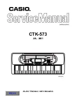
FILTER BLOCK
Since the sound signals from the DAC are stepped waveforms, the filter block is added to smooth the
waveforms.
POWER AMPLIFIER (IC101: LA4635)
The power amplifier is a two-channel amplifier with standby switch.
The following table shows the pin function of IC101.
.
o
N
n
i
P
l
a
n
i
m
r
e
T
t
u
O
/
n
I
n
o
i
t
c
n
u
F
1
D.C.
–
Terminal for a decoupling capacitor
2
IN 1
In
Channel 1 input
3
Pre GND
In
Ground (0 V) source
4
IN 2
In
Channel 2 input
5
STBY
In
Power control signal input. 0 V: Off, +9 V: On
6
P.P
In
Prevention of POP sound
7
VCC
In
+9 V source
8
OUT 2
Out
Channel 2 output
9
N.C.
–
Not used
10
Power GND
In
Ground (0 V) source
11
N.C.
–
Not used
12
OUT 1
Out
Channel 1 output
From DAC
To main volume
Summary of Contents for CTK-573
Page 14: ...13 Sub PCB JCM702 MA2M Top View 9 10...
Page 15: ...14 JCM702 CN1MA Top View Bottom View JCM702 CN2MA Top View Bottom View...
Page 16: ...15 SCHEMATIC DIAGRAMS Main PCB JCM702 MA1M 8 7 4 1 2 3 5 6...
Page 17: ...16 Sub PCB JCM702 MA2M 9 10...
Page 18: ...17 Console PCB JCM702 CN1M CN2M...
Page 19: ...18 Display PCB JCM702 LCD1M...