background image

— 1 —

SPECIFICATIONS

GENERAL

Keyboard:

49 standard-size keys, 4 octaves

Tones:

100

Polyphony:

12 notes maximum (6 for certain tones)

Auto accompaniment

Rhythm patterns:

100

Tempo:

Variable (236 steps,   = 20 to 255)

Chords:

2 fingering methods (CASIO CHORD, FINGERED)

Rhythm controller:

START/STOP, SYNCHRO/FILL-IN

Accomp volume:

0 to 9 (10 steps)

Song bank

Tunes:

100

Controllers:

PLAY/PAUSE, STOP, REW, FF, LEFT ON/OFF, RIGHT ON/OFF

Musical dictionary

Name display:

TONE, RHYTHM, SONG BANK name/number, keyboard settings name/value

Tempo:

Tempo value, metronome, synchro standby, beat indicator

Chord:

Chord name, Chord form

Fingering:

Fingering indicators, parts, pedal (The pedal indicator is for received MIDI

data only.)

Song bank status:

PLAY, PAUSE, REW, FF

Staff:

4 octaves with sharp and flat indications

Keyboard:

4 octaves

MIDI:

5 multi-timbre receive

Other functions

Transpose:

12 steps (–6 semitones to +5 semitones)

Tuning:

Variable (A4 = approximately 440 Hz 

±

 50 cents)

Volume:

0 to 9 (10 steps)

Terminals

MIDI terminals:

IN, OUT

Phones/Output terminal:

Stereo standard jack (Output is monaural.)
Output Impedance: 60 

Output Voltage: 5 V (RMS) MAX

Power supply terminal:

9 V DC

Power supply

Dual power supply system

Batteries:

6 AA-size batteries

Battery life:

Approximately 2 hours (SUM-3/R6P)/4 hours (AM3/LR6)

AC adaptor:

AD-5

Auto power off:

Turns power off approximately six minutes after last key operation. Can be
disabled manually.

Speaker output:

3.0 W (Output is monaural.)

Power consumption:

9 V --- 7.5 W

Dimensions (HWD):

958 

×

 310 

×

 132 mm (37-3/4 

×

 12-3/16 

×

 5-3/16 inches)

Weight:

Approximately 3.5 kg (7.7 lbs) (without batteries)

ELECTRICAL

Current drain with 9 V DC:

No sound output

95 mA

±

20 %

Maximum volume

680 mA

±

20 %

with 12 keys C4 to B4 pressed in Synth-Lead 1
Volume: 9 (Max.)

Phone output level (Vrms with 8 

 load each channel):

with key A4 pressed in Synth-Lead 1

95 mV

±

20 %

Speaker output level (Vrms with 4 

 load each channel):

with key C4 pressed in Synth-Lead 1

1050 mV

±

20 %

Output level (Vrms with 47 K

 load each channel):

with key C1 pressed in Synth-Lead 1

1100 mV

±

20 %

Minimum operating voltage:

5.7 V

Summary of Contents for CTK-411

Page 1: ...UME SYNCHRO FILL IN START STOP TEMPO CHORD BOOK ACCOMP VOLUME CASIO CHORD NORMAL M 0 1 2 3 4 5 6 7 8 9 m 7 M7 dim TONE RHYTHM SONG BANK STATUS MAIN VOLUME TEMPO aug sus4 5 add9 CLEAR RHYTHM TRANSPOSE...

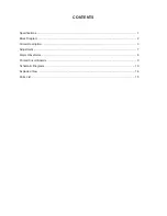
Page 2: ...CONTENTS Specifications 1 Block Diagram 2 Circuit Description 3 Adjustment 7 Major Waveforms 8 Printed Circuit Boards 9 Schematic Diagrams 10 Exploded View 14 Parts List 15...

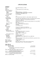
Page 3: ...0 Hz 50 cents Volume 0 to 9 10 steps Terminals MIDI terminals IN OUT Phones Output terminal Stereo standard jack Output is monaural Output Impedance 60 Output Voltage 5 V RMS MAX Power supply terminal...

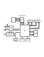
Page 4: ...et IC IC1 Oscillator X1 Q1 Power Supply Circuit Q101 Q103 D104 Power Amp LA4598 IC101 Filter Q105 Speaker L Speaker R Phones Output VC AVDD VCC DVDD APO MD0 MD7 MA0 MA17 DC 9 V IN DB4 DB7 COM1 COM16 S...

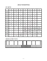
Page 5: ...olume Volume Down Up Down Up KO9 3 2 1 Start Synchro Chord Accomp Stop Fill in Book Volume KO10 6 5 4 Transpose Song Rhythm Tone Tune Bank KO11 9 8 7 Fingered CASIO Normal Power Off Chord KO12 FF Righ...

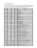
Page 6: ...t output 34 NC3 Not used 35 RSTB In Reset signal input 36 P24 RXD MIDI signal input 37 P25 TXD MIDI signal output 38 NMI In Power ON signal input Connected to 5 V 39 APO Out APO Auto Power Off signal...

Page 7: ...rom the CPU the LSI is capable of displaying up to 16 characters simultaneously The following table shows the pin functions of LSI3 Pin No Terminal In Out Function 1 22 SEG1 SEG40 Out Segment signal o...

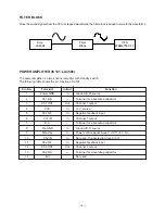
Page 8: ...minal In Out Function 1 Power GND In Ground 0 V source 2 Ch1 B S Terminal for a bootstrap capacitor 3 Ch1 OUT Out Channel 1 output 4 VCC In 9 V source 5 Ch1 N F In Negative feedback input 6 Ch1 IN In...

Page 9: ...oltmeter TP1 Adjust for 4 1 4 0 V reading on voltmeter under the temparature 20 25 C Make fine adjustment ac cording to the following in struction Watching the LCD at a 36 6 angle to the horizontal ad...

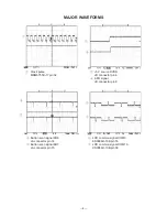
Page 10: ...V source DVDD JB connector pin 4 3 APO signal JB connector pin 8 2 3 4 Button scan signal KO6 JA connector pin 14 5 Button scan signal KO7 JA connector pin 15 4 5 6 LCD common signal COM9 KS0066U 10B...

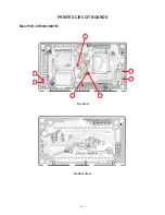
Page 11: ...9 Top View PRINTED CIRCUIT BOARDS Main PCB JCM444 MA1M Bottom View 3 2 7 6 4 5 1...

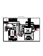
Page 12: ...10 SCHEMATIC DIAGRAMS Main PCB JCM444 MA1M 1 5 4 2 3 7 6...

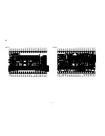
Page 13: ...11 Sub PCBs JCM444 MA2M MA3M...

Page 14: ...12 Keyboard PCBs JCM4911K KY1M KY2M...

Page 15: ...EG16 SEG17 SEG18 SEG19 SEG20 SEG21 SEG22 SEG23 COM15 COM14 COM13 COM12 COM11 COM10 COM9 COM16 COM15 COM14 COM13 COM7 COM6 COM5 COM4 COM3 COM2 COM1 SEG2 COM11 COM12 SEG39 SEG40 COM10 COM9 COM14 COM15 C...

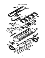
Page 16: ...14 EXPLODED VIEW 18 6 14 13 15 R 1 5 8 7 9 10 11 12 1 2 19 4 17 16 4 R 3 R 5 3 R 4 R 2...

Page 17: ...r spare parts department if you need these parts for refurbish 1 Prices and specifications are subject to change with out prior notice 2 As for spare parts order and supply refer to the GUIDEBOOK for...

Page 18: ...IODE ZENER MTZJ6 2A T77 T 1 C D104 D113 2390 1344 DIODE 1SS133T 77 T 11 X J101 3612 0665 JACK PHONE YKB21 5006 1 C J102 3501 7049 JACK POWER HEC2305 01 330 1 C J103 3501 4816 JACK DIN YKF51 5051 1 C K...

Page 19: ...CASIO TECHNO CO LTD Overseas Service Division 8 11 10 Nishi Shinjuku Shinjuku ku Tokyo 160 0023 Japan...

Reviews: