background image

— 17 —

DISPLAY

Trace

Zoom, V-Window, Sketch

ROMSIZE 8M bits
      ROM OK
checksum=

xxxxxxxx

RAMSIZE 32K byte
     RAM OK
RAMaddress

7FFF

RAMwrite

AA

RAMread

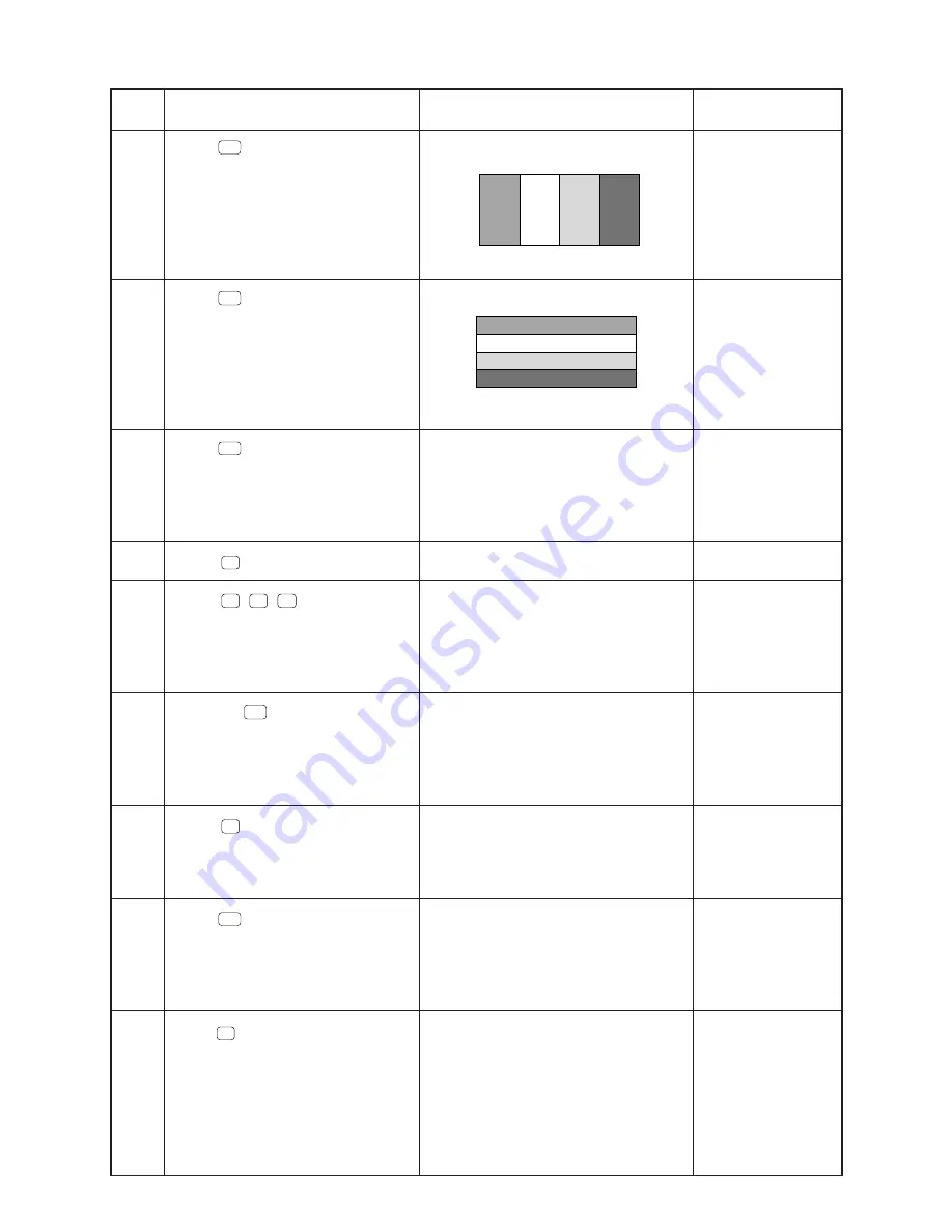
AA

Blue

No color

Orange

Green

NOTE

Check four colors.
If the colors do not
appear accurately,
perform the adjust-
ment mentioned in
page 5.

Check four colors

TEST mode menu

Check for keys

Check for keys.
To push the key
sequentially that is
being appeared in
the display.

TEST mode menu

ROM check

TEST mode menu

RAM check

OPERATION

Press 

EXE

 button.

Press 

EXE

 button.

Press 

EXE

 button.

Press 

3

 button.

Press

F1

F2

F3

..... buttons.

Press ..... 

EXE

 buttons.

Press 

6

button.

Press 

EXE

 button.

Press

7

button.

STEP

14

15

16

17

18

19

20

21

22

ZX935 Ver.X  TEST  MODE

1. Cnt
2. LCD
3. KEY
4. DET
5. TRS

6. ROM
7. RAM
8. CYC
0. Rst

ZX935 Ver.X  TEST  MODE

1. Cnt
2. LCD
3. KEY
4. DET
5. TRS

6. ROM
7. RAM
8. CYC
0. Rst

ZX935 Ver.X  TEST  MODE

1. Cnt
2. LCD
3. KEY
4. DET
5. TRS

6. ROM
7. RAM
8. CYC
0. Rst

Blue

No color

Orange

Green

Summary of Contents for CFX-9850G PLUS

Page 1: ...R MAY 1997 CFX 9850G PLUS without price CFX 9850G PLUS ZX 935A ...

Page 2: ...necting Two Units 10 4 2 Before Starting Data Communications 10 4 3 Performing Data Transfer Operation 11 4 4 To Send the Screen 14 4 5 Data Communication Precautions 15 5 OPERATION CHECK 16 6 DATA TRANSFER CHECK 19 7 PIN FUNCTION 20 8 TROUBLESHOOTING 21 9 OPERATION PROBLEMS 22 10 ERROR MESSAGE 23 11 SCHEMATIC DIAGRAMS 25 12 PARTS LIST 28 13 EXPLODED VIEW 29 ...

Page 3: ...k up Approximately 2 years The batteries that have been installed in this unit when user purchased it had been used in the factory test so it will be impossible to fully satisfy this specifications when these batteries are used Auto power off Power is automatically turned off approximately six minutes after last operation except when drawing dynamic graphs The calculator automatically turns off if...

Page 4: ...graph Use this mode to store graph functions and to draw multiple versions of a graph by changing the values assigned to the variables in a function 2 1 Modes To select an icon 1 Press MENU to display the Main Menu 2 Use the cursor keys to move the highlighting to the icon you want 3 Press EXE to display the initial screen of the mode whose icon you selected You can also enter a mode without highl...

Page 5: ...o draw cash flow Money and other types of graphs LINK Use this mode to transfer memory contents or back up data to another unit CONTrast Use this mode to adjust the color contrast of the display MEMory Use this mode to check how much memory is used and remaining to delete data from memory and to initialize reset the calculator 2 2 Color Contrast Adjustment Adjust the color whenever objects on the ...

Page 6: ...se the cursor and keys to move the pointer so it is next to the color ORANGE BLUE GREEN whose tint you want to adjust 2 Press the cursor key to give the color greener tint and the cursor key to give it an orange tint Holding down either key changes the setting at high speed To exit the color adjustment screen Press MENU to return to the Main Menu It is recommended that you always adjust the CONTRA...

Page 7: ...er from the calculator by pressing it in the direction indicated by arrow 1 and then sliding it in the direction indicated by arrow 2 4 Remove the four old batteries 5 Load a new set of four batteries making sure that their positive and negative ends are facing in the proper directions 6 Replace the back cover 7 Turn the calculator front side up and slide off its case Next press AC ON to turn on p...

Page 8: ...ress SHIFT OFF to turn the calculator off Warning Be sure to turn the unit off before replacing batteries Replacing batteries with power on will cause data in memory to be deleted 2 Making sure that you do not accidently press the AC ON key slide the case onto the calculator and then turn the calculator over 3 Remove the back cover from the calculator by pressing it in the direction indicated by a...

Page 9: ... RESET and then press EXE 3 Press F1 YES to reset the calculator or F6 NO to abort the operation without resetting anything 4 Press MENU If the display appears too dark or dim after you reset the calculator adjust the tint If the calculator stops operating correctly for some reason use a thin pointed object to press the P button on the back of the calculator This should make the RESET screen appea...

Page 10: ... connectors covered when you are not using them 4 2 Before Starting Data Communications In the Main Menu select the LINK icon and enter the LINK Mode The following data communication main menu appears on the display Select the LINK icon then press EXE button Image Set Indicates the status of the graphic image send features Off Graphic images not sent Monochrome Pressing F D sends graphic images in...

Page 11: ... from among previously selected data items and sends them BACK all memory contents including mode settings To send selected data items Press F1 SEL or F2 CRNT to display a data item selection screen SEL selects data item where cursor is located TRAN sends selected data items Use the and cursor keys to move the cursor to the data item you want to select and press F1 SEL to select it Currently selec...

Page 12: ...ents Overwrite Check 1 Yes Yes Yes Yes No Yes No No Yes No No No Password Check 2 Yes SYBL symbol input After inputting the password press EXE YES replaces the receiving unit s existing data with the new data NO skips to next data item 2 With password check If a file is password protected a message appears asking for input of the password Data item name 1 No overwrite check If the receiving unit a...

Page 13: ...by pressing AC To send backup data This operation allows you to send all memory contents including mode settings While the send data type selection menu is on the screen press F6 BACK and the back up send menu shown below appears Press F6 TRAN to start the send operation Press AC to return to the data communication Main Menu Sending Unit Receiving Unit The following shows what the displays of the ...

Page 14: ...reen you want to send 5 Set up the personal computer or Label Printer to receive data When the other unit is ready to receive press F D to start the second operation Selecting Monochrome for Image Set allows data to be sent to any CASIO Label Printer equipped with data communications capabilities Selecting Color allows data to be sent to Color Label Printer models only You cannot send the followin...

Page 15: ...able becomes disconnected if the parameters of the two units do not match or if any other communications problem occurs When this happens press AC to clear the error and correct the problem before trying data communications again If data communications are interrupted by AC key operation or an error any data successfully received up the interruption will be in the memory of the receiving unit An e...

Page 16: ...hile press ing F6 and ab c buttons Press 1 then EXE button Press EXIT button Press 2 button Press EXE button Press EXE button Press EXE button Press EXE button Press EXE button Press EXE button NOTE Reset TEST mode menu The contrast is changed automati cally Min Max default TEST mode menu Check for display Check for display Check for display Check for display Check for display STEP 1 2 3 4 5 6 7 8...

Page 17: ...ey sequentially that is being appeared in the display TEST mode menu ROM check TEST mode menu RAM check OPERATION Press EXE button Press EXE button Press EXE button Press 3 button Press F1 F2 F3 buttons Press EXE buttons Press 6 button Press EXE button Press 7 button STEP 14 15 16 17 18 19 20 21 22 ZX935 Ver X TEST MODE 1 Cnt 2 LCD 3 KEY 4 DET 5 TRS 6 ROM 7 RAM 8 CYC 0 Rst ZX935 Ver X TEST MODE 1 ...

Page 18: ... 18 OPERATION Press EXE button Press SHIFT then AC ON button DISPLAY OFF No display NOTE Reset End STEP 23 24 MEMORY CLEARED PRESS MENU KEY ...

Page 19: ... connect them using the cable SB 60 or SB 62 Perform STEP 1 4 described in 5 OPERATION CHECK before this check STEP STEP 4 of 5 OP ERA TION CHECK 1 2 3 4 5 6 7 8 9 10 OPERATION DISPLAY A unit B unit DISPLAY TRANSMIT Check 1 COM Check 2 VCCI Spec Test 0 Self 1 Send 2 Receive WAITING RECEIVING COM OK 0 Self 1 Send 2 Receive SENDING COM END 0 Self 1 Send 2 Receive TRANSMIT Check 1 COM Check 2 VCCI Sp...

Page 20: ... 6 V 81 VSS I GND 82 PI I 4 3 MHz clock input 83 PO O 4 3 MHz clock output 84 VDD I 6 V source 85 XO O Clock output 86 XI I Clock input 87 VCC I 6 V source 88 VREG2 O Voltage for main switch detection 89 90 TS1 TS2 Test terminals of factory purpose only 91 VSSR I GND 94 VSS I GND 96 ITOFF I Switching terminal from main switch 97 TEMU Test terminals of factory purpose only 98 SW I Receiving termina...

Page 21: ...r switch Poor connection on PC joiner Poor soldering on LSI capacitor or resistor Weak battery Dirt or poor contact on battery Poor contact on power switch Poor connection on PC joiner Defective LSI capacitor or resistor Poor contact between LCD and PCB Poor soldering on LSI Dirt on key contact Heavy key motion Poor soldering on LSI Defective LSI capacitor or resistor Constant contact is made on a...

Page 22: ... of Hang Up Should the unit hang up and stop responding to input from the keyboard press the P button on the back of the calculator to reset the memory Note however that this clears all the data in calculator memory Low Battery Message The low battery message apppears whenever you press AC ON to turn power on or MENU to display the Main Menu while the main battery power is below a certain level If...

Page 23: ...point where the error was generated and then correct the program 1234 Check the input numeric value and cor rect it When using memories check that the numeric values stored in memories are correct 5 Try using a smaller value for x x incre ment decrement 6 Try changing the tolerance tol when using Gauss Kronrod Rule or the num ber of divisions n when using Simpson s Rule to another value 7 Check th...

Page 24: ...m with cable connection or param eter setting during program data commu nications Problem with cable connection or param eter setting during data communications Problem with cable connection or param eter setting during data communications Memory of receiving unit became full during program data communications Message Mem ERROR Arg ERROR Dim ERROR Com ERROR TRANSMIT ERROR RECEIVE ERROR MEMORY FULL...

Page 25: ... 25 Main Block 1 11 SCHEMATIC DIAGRAMS ROM ...

Page 26: ... 26 Main Block 2 ...

Page 27: ... 27 Key Block To Main Block 1 ...

Page 28: ...30 LCD UNIT A240603B 2 HK 1 B 11 6408 0210 PC joiner L370 A413642 1 1 B COMPONENTS 12 6416 9340 Key contact rubber Z933 A240567 1 1 C N 13 6420 2330 Hard case Z935AE A240568 3 1 C 14 6416 9500 Battery holder A441594 1 1 X 15 6416 9380 Display plate Z933 A341011 1 1 C 16 6390 0432 Cap V332 A310765B 1 1 C 17 6413 5080 Button E L392 A313257 3 1 C 18 6413 5090 Button F L392 A313257 4 1 C N 19 6420 533...

Page 29: ...2 Remove the battery cover R 3 Remove the battery holder D then loosen the screw 4 Remove the lithium battery 5 Remove four main batteries 6 Loosen four screws 7 Open the lower case W using any opener 8 Loosen four screws 9 Loosen two screws 10 Loosen three screws S1 S2 S3 S4 S5 B1 B2 DISASSEMBLY 13 EXPLODED VIEW 1 2 ...

Page 30: ...23 25 24 22 20 19 21 18 17 4 6 7 LSI6 LSI5 30 13 EXPLODED VIEW 2 2 ...

Page 31: ...MA0500671A ...

Reviews: