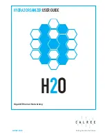
background image

— 48 —

10.

SCHEMATIC DIAGRAMS

Main block (PCB ASSY-A140806)-1/5

✽ 

Connection terminal with soldering-P101, P102

Unit

P101

no connection with soldering

no connection with soldering connected with soldering
connected with soldering 

BN-20 

BN-10

P102

X1:Ceramic oscillator for Main system clock (10.14 MHz)
X2:Crystal oscillator for Timer clock (32.768 KHz)

CPU

*BN-10:Z456
 BN-20:Z457

Summary of Contents for BN-10

Page 1: ...R BN 10 ZX 456 BN 20 ZX 457 NOV 1997 without price BN 20 ...

Page 2: ...eneral 24 4 2 Connecting the CASIO BN Unit to PC 25 4 3 PC sync for Windows Brief explanation 27 5 OPERATION CHECK 5 1 To enter the operation check mode 29 5 2 Operation Check 30 6 ERROR MESSAGES 38 7 TROUBLESHOOTING 40 8 LSI PIN FUNCTION 8 1 CPU 41 8 2 Gate Array 42 9 CIRCUIT EXPLANATION 9 1 Block Diagram 44 9 2 Power Supply 45 9 3 Function 46 10 SCHEMATIC DIAGRAMS 48 11 DISASSEMBLY 11 1 Disassem...

Page 3: ...alkaline batteries Type LR6 AM3 or optional AD A70140 AC adaptor Battery life Ambient Temperature 20 C BN 10 Approximately 100 hours of continuous display only in the CON TACTS Mode Approximately 80 hours with 55 minutes of continuous display only and 5 minutes of processing operation per hour in the CON TACTS Mode Approximately 500 minutes continuous connection of optional fax modem BN 20 Approxi...

Page 4: ... GND 2 1 V 2 0 Low battery message appears 1 6 V 2 0 Forced power off AC Adapter voltage T661 VCC T652 GND 4 5 V 2 0 Forced power off Auto power off Approximately 6 minutes after last key operation Operating temperature 0 C 40 C 32 F 104 F Dimensions Unfolded 11H 167W 162 5D mm 3 8 H 6 5 8 W 6 3 8 D Folded 22H 167W 88D mm 7 8 H 6 5 8 W 3 1 2 D Weight BN 10 Approximately 270 g 9 5 oz including batt...

Page 5: ...2 GENERAL GUIDE 2 1 Appearances and Display Indicators Display Mode keys Cursor keys Option port Keyboard Lock Mini Cradle port AC adaptor connector P button Battery switch RESET button Option lock switch ...

Page 6: ...aracter will be interpreted as a command SEARCH Indicates that the displayed data is the result of a search operation Low battery warning Indicates you are currently in the secret memory area Data runs off the bottom of the screen Scroll displayed data by pressing and Fields and Items In the sections that cover the personal data storage functions of the BN Unit you will come across the terms field...

Page 7: ...ter the MAIL FAX Mode when you press the MAIL FAX key or when you select MAIL FAX from the Mode Menu See the manual that comes with the modem for operating procedures and other details To enter a mode by pressing a mode key Press one of the mode keys located under the BN Unit s display to enter the corresponding mode To enter a mode using the Mode Menu 1 Press the MENU key to display the Mode Menu...

Page 8: ...ld of a SCHEDULER item while other parts such as TIME and DATA fields remain unchaged Using the Menu Bar The menu bar provides you with a selection of pull down menus containing commands that are very similar to those found in many desktop computer applications The availability of the menu bar the type of pull down menus it contains and the contents of the pull down menus depend on the mode you ar...

Page 9: ... the unit Doing so can remove the figures printed on the case or otherwise damage the case finish The contents of this manual are subject to change without notice CASIO COMPUTER CO LTD assumes no responsibility for any loss or claims by third parties that may arise from the use of this product Data Errors The BN Unit performs a self check routine whenever you turn it on The message showm below app...

Page 10: ...uage you want to use 5 Press OK to register your setting and close the dialog box Pressing ESC in the above step closes the dialog box without changing anything To turn the key input tone on and off 1 Press MENU BAR to display the menu bar 2 Use to highlight SYSTEM and then press 3 Use to highlight SOUND and then press OK 4 In the dialog box that appears use to select KEY TONE The selected setting...

Page 11: ...at you are unable to store new data even after you have deleted some data from memory When this hap pens you need to perform the following memory management procedure which cleans up and rearranges unused memory to make it available for storage of more data Note When you need to perform memory management depends entirely how often you delete data from memory and store new data The more you delete ...

Page 12: ...haracter descriprion CONTACTS Approximately 23 424 items 10 736 for the BN 10 under the following conditions 8 character name 10 character home phone number 10 character home fax number 20 character home address Approximately 7 808 items 3 578 for the BN 10 under the following conditions 8 character name 10 character business phone number 10 character business fax number 40 character business addr...

Page 13: ...rn it off manually Leaving the backlight on for long periods greatly reduces battery life Backlight Operation BN 20 only The electro luminescent backlight of the BN 20 Unit helps to keep your on screen data bright and easy to read at all times There are two different operations you can use to turn on the backlight One turns the backlight on for about 15 seconds while the other procedure leaves the...

Page 14: ...lly turns off power whenever you do not perform any key operation for about 6 minutes Use the procedure described under To turn power on and off de scribed in the next page to turn power back on AC Adaptor Caution Use the AC adaptor only with a power outlet whose voltage matches that marked on the adaptor Do not plug the adaptor into an extension shared by other appliances Doing so creates the dan...

Page 15: ...to operate it under AC adaptor power while batteries are not loaded or battery power is low This is done in order to protect against corruption of memory contents caused by a sudden drop in power when the AC adaptor is unplugged from the BN Unit Always unplug the AC adaptor from the BN Unit before replacing batteries 1 Connect the AC adaptor into the jack on the left side of the BN Unit 2 Plug the...

Page 16: ...ON BN 20 ON OFF to turn on power 2 Use a thin pointed object to press the RESET button on the back of the BN Unit This causes the contrast adjustment screen to appear If the contrast adjustment screen does not appear when you press the RESET button slide the battery switch to the REPLACE BATTERIES position and remove the battery compartment cover Use a thin pointed object to press the P button and...

Page 17: ...ing OK in the above step starts the actual reset procedure 6 After the reset procedure is complete use the and cursor keys to highlight the display message language you want to use 7 Press OK to complete the procedure This enters the CLOCK Mode 8 Check the Home Time setting and make changes if necessary page 19 Following are the initial settings of the BN Unit after you perform the RESET operation...

Page 18: ...n the back of the BN Unit to the REPLACE BATTERIES position 3 While pressing at the points marked A in the illustration slide the battery compartment cover in the direction indicated by the arrow to remove it 4 Remove both of the old batteries 5 Load two new batteries making sure that their positive and negative ends are facing in the proper directions 6 Taking care not to damage its tabs replace ...

Page 19: ...not solve the problem refer to Troubleshooting on page 40 10 In response to the message that appears CHECK YOUR HOME TIME SETTING AND COR RECT IT IF NECESSARY press OK This enters the CLOCK Mode 11 Check the Home Time setting and make changes if necessary as described below 12 Perform the procedure under To set the on screen message language on page 10 to specify the language you want to use Enter...

Page 20: ...IME and then press OK The DST indicator shows which cities for which daylight saving time is turned on See page 21 for details on turning daylight saving time on and off 3 Use and to select the name of the city you want to use as your Home Time city or World Time City Press and to scroll the list of city names page by page To jump to a city name input the letter that the name begins with See the A...

Page 21: ...e finished making the settings you want press OK to store them Pressing OK resets the seconds count to 00 Other CLOCK Mode Settings The following procedures describe how to make other settings that help you configure the CLOCK Mode suit your needs To switch between 12 hour and 24 hour time formats In the CLOCK Mode execute the EDIT menu s 12 24 FORMAT command Executing the above command toggles th...

Page 22: ...command 2 Use and to select the date format you want to use 3 Press OK to register your setting The date format you select with the above procedure is applied anytime a date appears on the display of the BN Unit Using the Daily Alarm You can set an alarm time to cause an alarm to sound whenever that time is reached in your Home Time city To set an alarm time 1 In the CLOCK Mode execute the EDIT me...

Page 23: ...he Daily Alarm Whenever the alarm time is reached while the Daily Alarm is on a buzzer sounds for about 20 seconds or until you press any of the BN Unit s keys To turn the Daily Alarm on and off 1 Execute the SYSTEM menu s SOUND command 2 In the dialog box that appears use to select DAILY The selected setting is the one whose on or off setting appears as 3 Use and to turn the alarm on and off 4 Pr...

Page 24: ... Another BN Unit Importing Data from Another CASIO Digital Diary Model PC sync for Windows cannot be used to send data from your computer to another CASIO Digital Diary model See the manual that comes with PC sync for Windows for a list of supported CASIO Digital Diary models required PC system configuration and cable requirements Note If an imported spreadsheet has more than 32kb of data anything...

Page 25: ...ur computer s serial port RS 232C The serial port is normally labeled COM1 COM2 COM3 or COM4 If the serial port on your computer does not match the Mini Cradle s connector you need to purchase an adaptor See the documentation that comes with your computer for details To connect the Mini Cradle to the CASIO BN Unit 1 Make sure that the power of both the BN Unit and your computer is turned off 2 Ope...

Page 26: ...nap securely into place Do not apply undue force Doing so can damage the Mini Cradle connector or BN Unit port To disconnect the Mini Cradle from the CASIO BN Unit 1 Make sure that the power of both the BN Unit and your computer is turned off 2 While squeezing the buttons on both sides of the connector pull it straight out from the Mini Cradle port to remove it 3 Close the BN Unit s port cover Squ...

Page 27: ...PPED Pressing ESC button once more the MENU mode display will appear 2 High speed data transfer The default transfer speed is 38400 b p s The data transfer speed can be set to 1200 38400 b p s 1200 2400 4800 9600 14400 19200 28800 and 38400 b p s because BN Units have more memory capacity than another CASIO Digital Diary The high speed data transfer causes often to miss the data transfer Therefore...

Page 28: ...nsfer even if the transfer is performed with 38400 b p s 4 After data transfer the MENU mode display will appear with BN Unit Note Backup files always have the extension bak and cannot be edited i e you cannot open them choosing File then Open Remarks 1 Select the default PORT COM1 PORT ordinarily Otherwise the data transfer will not be per formed Select another PORT if the data transfer is not pe...

Page 29: ...ual 1 Slide the battery switch on the back of BN Unit to the REPLACE BATTERIES position 2 Remove the battery cover 3 Slide the battery switch on the back of BN Unit to the NORMAL OPERATION position 4 Turn the power on 5 Pressing the RESET button on the back of the BN Unit using a thin pointed object the contrast adjustment screen appears 6 Short two central golden pads as shown below You had bette...

Page 30: ...ck Check data transfer between BN Unit and PC referring to 4 DATA COMMU NICATION of this manual 7 MODEM CHECK The MODEM BW 100 is necessary for this check But formal MODEM BW 100 don t exist now After the formal marketed BW 100 appears the techni cal information for BW 100 will be supplied 5 2 1 DISPLAY CHECK 1 Press 1 button The following display appears DISPLAY MENU 1 PATTERN 1 2 PATTERN 2 8 PAT...

Page 31: ...ATTERN 4 Press ESC then 4 button The following display appears ALL DISPLAY 6 PATTERN 5 Press ESC then 5 button The following display appears NO DISPLAY 7 DD RAM CHECK Press ESC then 6 button The following display appears SHIFT CAPS ACC COMMAND SEARCH SHIFT CAPS ACC COMMAND SEARCH ...

Page 32: ...con trast value 10 Contrast Check Touch ESC Hard lcon Them Test END Touch Key Then DRANK Touch Key Then THIN LIGHT DARK THIN LIGHT Contrast Value 10 STRIPE PATTERN 7 Press ESC then 9 button The following display appears REVERSED STRIPE A Press ESC button twice Doing so TEST MENU display appears 5 2 2 MEMORY CHECK 1 Pressing 2 button the following MEMORY MENU appears SHIFT CAPS ACC COMMAND SEARCH M...

Page 33: ...this ROM is not mounted NC is displayed instead of 1M CS4 1M indicates that the flash ROM of memory capacity 1M byte is mounted on Main PC board as LSI306 NC is displayed in stead of 1M because this LSI306 is not mounted with BN 10 XXX44 is not displayed with BN 10 also XXX5 4 If OKF5 4 is displayed the flash ROM of LSI304 LSI306 is formatted and have no memories If NGF5 4 is displayed the flash R...

Page 34: ...XXXXX OKF4 OKW4 OKR4 BANKXX OKW5 4 indicates that the data for this check could be written into LSI304 306 without prob lems NGW5 4 indicates that the data for this check could not be written into LSI304 306 OKR5 4 indicates that these data could be read from LSI304 306 without problems NGR5 4 indicates that these data could not be read from LSI304 306 CS4 NC is displayed in stead of CS 1M with BN...

Page 35: ...is check halfway press OK 71 button Then KEY MENU display described above appears 4 Press OK 71 button Then KEY MENU display appears Next pressing ESC button TEST MENU display appears 5 2 5 OTHER CHECK 1 Pressing 8 button the following OTHERS MENU display appears 19 20 21 22 23 24 25 26 27 28 29 11 18 14 17 16 15 12 13 30 31 32 33 34 35 36 37 38 39 40 41 42 43 44 45 46 47 48 49 50 51 52 63 64 65 6...

Page 36: ...MONITOR OPEN LOCK BTTERY SW CARDLOCK SW ON OFF LOW BATTERY1 LOW BATTERY2 CRADLE SW Sliding battery switch and lock switch for MODEM on the back of BN Unit positions of two upper asterisks shown above change Pressing START button on the cradle after setting it to BN Unit position of a lower asterisk shown above changes Then pressing ESC button OTHERS MENU display appears 7 CS6 DOWN LOAD The special...

Page 37: ...nto the jack and its output voltage is less than DC 4 4V the following display appears DET5V Then pressing ESC button OTHERS MENU display appears 9 EL ON CHECK BN 20 only Pressing 8 button the blue back light is emitted EL OFF CHECK BN 20 only Pressing 9 button the blue back light is disappeared Then pressing ESC button TEST MENU display appears A END END Pressing 10 button the following display a...

Page 38: ...age that appears for about one second After that the dia log box closes and the data is stored without the alarm Change the alarm time to one that is not yet used Wait until some of the existing alarms are used or delete alarms you do not need to make room for new ones Enter the secret memory area to view details about the alarm This is a reminder message so no action by you is required Make the a...

Page 39: ... causes the data in the cells to be deleted The spreadsheet you are working with in the SPREADSHEET Mode is larger than the allowable maxi mum Action First try performing the memory management operation to see if more memory can be made available If this message still appears it means that memory is really full Delete data you no longer need to make room for more data Press OK to delete the cells ...

Page 40: ...N Unit for details on the reset procedure 5 After adjusting the display con trast and confirming that a mes sage is visible on the screen press ESC to clear the mes sage PROBLEM Nothing appears on the display when power is turned on The BN Unit does not operate normally after batteries are re placed 7 TROUBLESHOOTING Power Supply Display Contrast Display is totally black Display contrast is too da...

Page 41: ...lash ROM LSI308 62 VSEL1 I Power supply 5 V to CPU 63 VSEL2 I Power supply 3 V to CPU 67 CS8B O not used 68 CS7B O Chip select signal to MASK ROM LSI301 and LSI308 69 CS6B O Chip select signal to LSI for MODEM passing trough Gate array 70 CS5B O Chip select signal to flash ROM LSI304 71 CS4B O Chip select signal to flash ROM LSI306 72 CS3B O Control signal to data latch IC IC151 for control of pow...

Page 42: ...MODEM 25 REGB O not used 26 V5A1 O Address bus to ROM for MODEM 27 BVD2 I DR OK signal from MODEM in response to ER 28 V5A0 O Address bus to ROM for MODEM 29 BVD1 I CD Information signal from MODEM to BN Unit Detection of carrier 30 VSS Ground for Gate array 31 CD2B I not used 32 V5D8 I O not used 33 V5D1 I O Data bus for ROM of MODEM 34 V5D9 I O not used 35 V5D2 I O Data bus for ROM of MODEM 36 V...

Page 43: ...I DR OK signal from PC in response to ER 111 CS I CS OK NG signal from PC in response to RS 112 RD I Data to send from PC to BN Unit passing through the cradle 113 SD O Data to send from BN Unit to PC passing through the cradle 114 V5A19 O not used 115 V5A14 O Address bus to ROM for MODEM 116 V5A18 O Address bus to ROM for MODEM 117 VSS Ground for Gate array 118 V5A13 O Address bus to ROM for MODE...

Page 44: ...Adapter AD A70140 34 5 kHz Common TAB LSI3 Clock KEYS Buzzer KI KO TX RX Clock CPU LSI1 10 14 MHz 32 768 kHz Data bus Gate array LSI2 RX TX TX RX TX RX RX TX MODEM BW 100 Line driver receiver IC501 TX RX TELEPHONE RX TX MINI CRADLE Personal computer CPU Gate array etc CPU START BUTTON RS 232C Address bus 1 Mbits S RAM LSI303 16 Mbits MASK ROM LSI301 8 Mbits FLASH ROM LSI304 BN 20 only 8 Mbits FLAS...

Page 45: ... Gate array Detection of low adapter voltage 4 4 V V3SYS VLCO V5EXT 5 V APO OFF BLD2 to CPU to CPU Q624 IC602 Q623 Q604 D604 20 5 23 V VOUT TH D D Converter Q605 EVOL1 EVOL5 from CPU PORT4 from CPU FUSE F601 Battery 3 V IC601 BLD1 Low battery Forced power off 2 1 V 1 6 V APO OFF POWER SUPPLY V5EXT to MODEM V5SYS to CPU Gate array etc DC AC Inverter for EL Line receiver driver V2SYS to CPU Buzzer K...

Page 46: ...20 with BN Unit itself and saved in flash ROM LSI308 concerning MODEM BW 100 And LSI301 is a mask ROM for operation Data saved in a flash ROM are not deleted even if power is not supplied Therefore the lithium battery for memory backup is not necessary with BN Unit It is easy to write data using the flash ROM like RAM And the overall deletion of data is performed instantly using the flash ROM diff...

Page 47: ...ntermeasure against EMI Electro Magnetic Interference with BN Unit The copper films for shield and wires connecting between grounds on PC board are used for counter measure against EMI If these parts doesn t exist data transfer between BN Unit and MODOEM PC will not be performed 9 3 5 EL Electroluminescence driver IC IC701 BN 20 only This IC is a DC AC inverter for EL V5SYS terminal voltage DC 5 V...

Page 48: ... soldering P101 P102 Unit P101 no connection with soldering no connection with soldering connected with soldering connected with soldering BN 20 BN 10 P102 X1 Ceramic oscillator for Main system clock 10 14 MHz X2 Crystal oscillator for Timer clock 32 768 KHz CPU BN 10 Z456 BN 20 Z457 ...

Page 49: ... 49 Main block PCB ASSY A140806 2 5 FM3416 Gate array ...

Page 50: ... 50 Main block PCB ASSY A140806 3 5 1 KEY81 CHECK TRANS KEY is a key for TEST not one for users ...

Page 51: ... 51 Main block PCB ASSY A140806 4 5 LINE DRIVER RECEIVER ...

Page 52: ... 52 Main block PCB ASSY A140806 5 5 AC Adapter Batteries ...

Page 53: ... R330 LSI308 MASK ROM FLASH ROM used not used used not used used not used not used used Unit s Name LSI304 LSI306 R335 R336 BN 10 BN 20 used used used not used not used not used used not used At first FLASH ROM will be used then MASK ROM will be used ...

Page 54: ...d used 1 13 not used used not used used 1 14 used not used not used used 1 15 not used not used not used used 1 16 used used not used R728 used used used used used used used not used not used Actually bias for LCD is set to 1 13 R718 R715 C724 C725 Bias voltage controller for LCD driver This circuit EL and EL driver is used only with BN 20 is not used with BN 10 ...

Page 55: ... 55 Display block LCD ASSY A140809 A140814 2 3 LCD common terminal driver ...

Page 56: ... 56 Display block LCD PCB ASSY A140809 A140814 3 3 LCD segment terminal driver ...

Page 57: ... 57 Cradle A140805 BN 10 20 PCB Z456 1 shielded ...

Page 58: ...01 and CN102 as shown below 12 Remove two flat cables e f from two connectors CN301 and CN302 as shown above 13 Remove a screw S3 14 Remove the inner case 15 Remove the rubber key for P button k taken in the inner case 16 Remove the cover c and tiny spring j Take care not to lose the tiny spring j 17 Remove the FPC H from the connector CN601 18 Remove the black wire WIR1 soldered to the main PCB A...

Page 59: ...emove the metal fittings M 8 Remove six screws S7 two screws S8 and two washers W2 Next remove the upper case C and then peel the frame G from C while taking out this frame from two holes A of this upper case 9 Remove two wires WIR2 soldered to PCB ASSY 3 10 Peel the buzzer I from the inner case E 11 Take out the LCD ASSY F after peeling the inner case E from PCB ASSY 12 Disassemble the LCD ASSY r...

Page 60: ...mon 1 C N IC602 2105 6174 IC MOS XC61AC1602PR Common 1 C N IC603 2105 6352 IC MOS XC6372B502PR Common 1 C N IC604 2105 6209 IC MOS XC61AC4502PR Common 1 C N IC605 2105 6350 IC MOS XC62FP3302PR Common 1 C N IC606 2105 6349 IC MOS XC62FP2202PR Common 1 C IC607 2105 5999 IC MOS XC6383F501MR Common 1 C IC609 2114 4683 IC MOS TC74HC4066AFS EL Common 1 C IC610 2105 6167 IC MOS TC7S66F TE85R Common 1 C N...

Page 61: ...19 3122 2380 BUZZER EFB S55C41A8 Common 1 C N 20 6421 5680 GUIDE SHAFT A443094 1 Common 1 C N 21 6421 5701 TAPE SHIELD A443126A 1 Common 1 C N 22 6421 5711 TAPE SHIELD A443127A 1 Common 1 C N 23 6421 6670 CONTACT HOLD SUB ASSY A342102 1 Common 1 C N 24 6421 5730 TAPE SHIELD A443130 1 BN 20 2 C UPPER CASE A ASSY A140808 N 25 6420 8801 BUTTON A140724A 1 Common 1 C N 26 6420 8810 CASE UPPER A140725 1...

Page 62: ...030 LEVER LOCK A341765 1 Common 1 C N 45 6420 9220 CONNECTOR FFC A442768 1 Common 1 C N 46 6420 9230 CONNECTOR FFC A442769 1 Common 1 C N 47 6420 8780 KNOB ASSY A442934 1 Common 1 C N 48 6420 8790 KNOB ASSY A442935 1 Common 1 C N 49 6420 9130 RUBBER FOOT A442751 1 Common 2 C N 50 6420 9261 SPRING A442943A 1 Common 1 X 51 6391 8831 RUBBER KEY A311024A 1 Common 2 C OTHERS N 52 1014 9838 FLOPPY DISK ...

Page 63: ...of EXPLODED VIEW 2 2 Refer to KEY ARRANGEMENT of EXPLODED VIEW 2 2 1 2 3 4 4 5 6 6 7 8 9 10 10 11 12 13 14 15 16 17 18 19 20 21 22 23 24 26 27 28 29 30 34 36 37 38 39 40 41 42 43 44 45 46 47 48 49 49 50 51 51 S1 S1 S2 S3 S4 W1 W1 AX1 AX1 WIR2 S7 S7 S8 W2 W2 WIR3 WIR4 WIR1 J601 CN301 CN302 ...

Page 64: ...YMBOL DEL OK Z X C V B N M ON OFF LIGHT 1 2 31 32 33 25 35 BN 10 ON OFF ON No light mark LIGHT OFF PCB ASSY PCB ASSY TAB TAB LCD ADHESIVE TAPE ELECTRO LUMINESCENCE HEAT SEAL ADHESIVE TAPE LCD COMMON LCD SEGMENT ADHESIVE TAPE 4 HEAT SEAL 6 3 8 12 5 3 7 9 10 11 BN 10 No electro luminescence segment side common side CROSS SECTION of LCD ASSY F ...

Page 65: ...CASIO TECHNO CO LTD Overseas Service Division 8 11 10 Nishi Shinjuku Shinjuku ku Tokyo 160 0023 Japan ...

Reviews: