background image

INTRODUCTION

Basic instructions

Machine safety

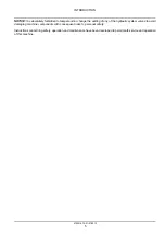
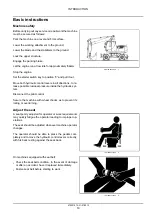
Before carrying out any service or repair work the machine
must be secured as follows:

Park the machine on a level and firm surface.

Lower the working attachment to the ground.

Lower the blade and the stabilizers to the ground.

Lock the upper structure.

Engage the parking brake.

Let the engine run at low idle for approximately

5 min

.

Stop the engine.

Set the starter switch key to position “0” and pull it out.

Move both hydraulic control levers in all directions, to re-
lease possible residual pressure inside the hydraulic sys-
tem.

Disconnect the pilot control.

Secure the machine with wheel chocks as to prevent its
rolling or overturning.

SMIL12WEX0021AA

1

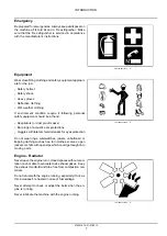
Adjust the seat

A seat poorly adjusted for operator or work requirements
may quickly fatigue the operator leading to improper op-
erations.

The seat should be adjusted whenever machine operator
changes.

The operator should be able to press the pedals com-
pletely and to move the hydraulic control levers correctly,
with his back resting against the seat back.

TULI12WEX2024AA

2

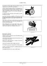
On machines equipped with seat belt:

• Check the seat belt condition. In the event of damage

or after an accident, have it replaced immediately.

• Fasten seat belt before starting to work.

TULI12WEX2025AA

3

47500167A 31/01/2013

19

Summary of Contents for WX148

Page 1: ...VICE MANUAL 1 1 WX148 Wheeled Excavator SERVICE MANUAL WX148 Wheeled Excavator 1 1 Part number 47500167 English January 2013 Copyright 2013 CNH Europe Holding S A All Rights Reserved Part number 47500...

Page 2: ...SERVICE MANUAL WX148 47500167A 31 01 2013 EN Find manuals at http best manuals com search s CASE 47500167...

Page 3: ...3 21 155 Powershift transmission internal components 21 4 Four Wheel Drive 4WD system 23 23 314 Drive shaft 23 1 Front axle system 25 25 100 Powered front axle 25 1 25 102 Front bevel gear set and di...

Page 4: ...ating bucket hydraulic system 35 11 35 703 Stabilizer hydraulic system 35 12 35 730 Positioning arm hydraulic system 35 13 35 736 Boom hydraulic system 35 14 35 737 Dipper hydraulic system 35 15 35 73...

Page 5: ...ol 55 8 55 050 Heating Ventilation and Air Conditioning HVAC control system 55 9 55 100 Harnesses and connectors 55 10 55 110 Electrical rotary joint 55 11 55 302 Battery 55 12 55 404 External lightin...

Page 6: ...ab bodywork and decals 90 90 118 Protections and footboards 90 1 90 120 Mechanically adjusted operator seat 90 2 90 150 Cab 90 3 47500167A 31 01 2013 Find manuals at http best manuals com search s CAS...

Page 7: ...47500167A 31 01 2013 Find manuals at http best manuals com search s CASE 47500167...

Page 8: ...INTRODUCTION 47500167A 31 01 2013 1 Find manuals at http best manuals com search s CASE 47500167...

Page 9: ...l safety 6 Product overview 15 Basic instructions 19 Dimension 20 Weight 26 General specification 27 Capacities 33 General specification 35 Consumables 40 Product identification 41 47500167A 31 01 201...

Page 10: ...receded by the above mentioned key words DANGER and WARNING can cause serious accidents or the death of the persons involved Moreover this manual contains some instructions pre ceded by the words NOTE...

Page 11: ...nctional disorders especially those affecting the safety of the ma chine should therefore be rectified immediately The Excavator is intended to be used in digging and loading operation with bucket or...

Page 12: ...etting of any of the hydraulic system valves to avoid damaging machine components with consequent risks to personal safety Instructions concerning safety operation and maintenance have been developed...

Page 13: ...m any other position than the operator s seat TULI12WEX2004AA 1 Never carry out any operation on the machine when the engine is running except when specifically indicated Stop the engine and ensure th...

Page 14: ...oustic ears protections Goggles with lateral shield or masks for eyes protection Do not wear rings wristwatches jewels unbuttoned or flapping clothing such as ties torn clothes scarves open jackets or...

Page 15: ...ve the cap with hot engine wear safety clothes and equipment then loosen the cap slowly to re lieve the pressure gradually When checking the fuel oil and coolant levels use ex clusively explosion proo...

Page 16: ...r pressure can accidentally be pierced when the heat expands beyond the area immediately heated Arrange for fire resistant temporary shields to protect hoses or other components during welding Have an...

Page 17: ...uter sheath will allow the water pen etration Concealed corrosion of the wire reinforcement will subsequently occur along the hose length with resul tant hose failure Ballooning of the hose indicates...

Page 18: ...ater to rinse your mouth Consult a doctor EYES Rinse abundantly with water for 15 min and con sult a doctor When the electrolyte of a battery is frozen it can ex plode if you attempt to charge the bat...

Page 19: ...or oil splashes can cause slipping and therefore acci dents clean immediately and accurately the areas even tually smeared Always tighten the safety plugs of fuel tank and hydraulic oil tank firmly N...

Page 20: ...istol complete with extension and pressure switch of control TULI12WEX2020AA 18 Cleaning Clean the exterior of all components before carrying out any form of repair Dirt and dust can reduce the effici...

Page 21: ...tion rests and pure an tifreeze Fuel Filter elements oil and fuel filters Filter elements air filters Battery Also polluting rags paper sawdust and gloves must be disposed in compliance with the same...

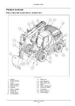
Page 22: ...e doors 2 Bucket cylinder 12 Rear stabilizers 3 Dipper 13 Rear axle wheels 4 Dipper cylinder 14 Cabin 5 Second boom 15 Stairs storage box 6 Cylinder 16 Front axle wheels 7 Boom cylinders 17 Front blad...

Page 23: ...10 Rear stabilizers 2 Bucket cylinder 11 Rear axle wheels 3 Dipper 12 Cabin 4 Dipper cylinder 13 Stairs storage box 5 Boom 14 Front axle wheels 6 Boom cylinder 15 Front blade 7 Engine cover 16 Upper s...

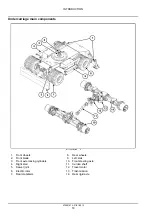
Page 24: ...r conditioning air system 3 Protection handrails 13 Batteries 4 Main valve 14 Air filter 5 Fuel tank 15 Pilot control assy 6 Hydraulic oil tank 16 Diesel engine 7 Hydraulic pumps 17 Cabin installation...

Page 25: ...Front wheels 8 Rear wheels 2 Front blade 9 Left stair 3 Front axle locking cylinders 10 Front steering axle 4 Right stair 11 Cardan shaft 5 Swivel joint 12 Travel motor 6 Electric rotor 13 Trasnmissio...

Page 26: ...de the hydraulic sys tem Disconnect the pilot control Secure the machine with wheel chocks as to prevent its rolling or overturning SMIL12WEX0021AA 1 Adjust the seat A seat poorly adjusted for operato...

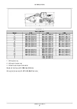
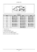
Page 27: ...8 mm 324 3 in 8248 mm 324 7 in 8217 mm 323 5 in B2 8238 mm 324 3 in 8248 mm 324 7 in 8217 mm 323 5 in B3 8215 mm 323 4 in 8238 mm 324 3 in 8245 mm 324 6 in C 3181 mm 125 2 in D 5978 mm 235 4 in 5988 m...

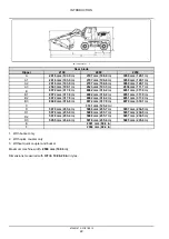
Page 28: ...323 5 in B2 8238 mm 324 3 in 8248 mm 324 7 in 8217 mm 323 5 in B3 8215 mm 323 4 in 8238 mm 324 3 in 8245 mm 324 6 in C 3181 mm 125 2 in D 5978 mm 235 4 in 5988 mm 235 7 in 5957 mm 234 5 in D1 5978 mm...

Page 29: ...7 0 in B2 8072 mm 317 8 in 8082 mm 318 2 in 8051 mm 317 0 in B3 8049 mm 316 9 in 8072 mm 317 8 in 8079 mm 318 1 in C 3181 mm 125 2 in D 5978 mm 235 4 in 5988 mm 235 7 in 5957 mm 234 5 in D1 5978 mm 23...

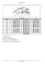
Page 30: ...in 8058 mm 317 2 in 8015 mm 315 6 in B2 8012 mm 315 4 in 8056 mm 317 2 in 8023 mm 315 9 in B3 7984 mm 314 3 in 8017 mm 315 6 in 8075 mm 317 9 in C 3181 mm 125 2 in D 5752 mm 226 5 in 5798 mm 228 3 in...

Page 31: ...317 4 in B2 8012 mm 315 4 in 8043 mm 316 7 in 8061 mm 317 4 in B3 7984 mm 314 3 in 8017 mm 315 6 in 8075 mm 317 9 in C 3181 mm 125 2 in D 5752 mm 226 5 in 5783 mm 227 7 in 5801 mm 228 4 in D1 5752 mm...

Page 32: ...0 8 in B2 7846 mm 308 9 in 7877 mm 310 1 in 7895 mm 310 8 in B3 7818 mm 307 8 in 7851 mm 309 1 in 7909 mm 311 4 in C 3181 mm 125 2 in D 5752 mm 226 5 in 5783 mm 227 7 in 5801 mm 228 4 in D1 5752 mm 22...

Page 33: ...0 lb 15550 kg 34281 9 lb 2950 mm 116 1 in 16400 kg 36155 8 lb 15850 kg 34943 3 lb 15600 kg 34392 1 lb Monoboom version weights Dipper Front blade and rear stabilizers Rear stabilizers Rear blade 2100...

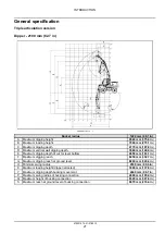
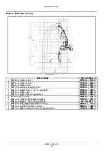
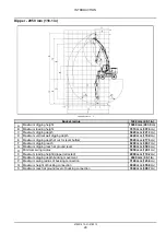
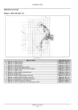
Page 34: ...m digging depth of cut for level bottom 4650 mm 183 1 in F Maximum digging reach 8450 mm 332 7 in G Maximum digging reach at ground level 8240 mm 324 4 in H Minimum swing radius 2530 mm 99 6 in K Maxi...

Page 35: ...level bottom 5000 mm 196 9 in F Maximum digging reach 8790 mm 346 1 in G Maximum digging reach at ground level 8590 mm 338 2 in H Minimum swing radius 2660 mm 104 7 in K Maximum loading height dipper...

Page 36: ...r level bottom 5520 mm 217 3 in F Maximum digging reach 9290 mm 365 7 in G Maximum digging reach at ground level 9100 mm 358 3 in H Minimum swing radius 3050 mm 120 1 in K Maximum loading height dippe...

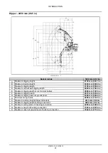
Page 37: ...f cut for level bottom 4500 mm 177 2 in F Maximum digging reach 8180 mm 322 0 in G Maximum digging reach at ground level 7960 mm 313 4 in H Minimum swing radius 2770 mm 109 1 in K Maximum loading heig...

Page 38: ...r level bottom 4890 mm 192 5 in F Maximum digging reach 8510 mm 335 0 in G Maximum digging reach at ground level 8300 mm 326 8 in H Minimum swing radius 2800 mm 110 2 in K Maximum loading height dippe...

Page 39: ...r level bottom 5420 mm 213 4 in F Maximum digging reach 9000 mm 354 3 in G Maximum digging reach at ground level 8800 mm 346 5 in H Minimum swing radius 3050 mm 120 1 in K Maximum loading height dippe...

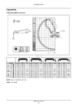
Page 40: ...2 1 3 7 2 4 4 5 2 9 5 5 3 9 Z2 3 7 2 5 1 6 3 9 2 8 1 8 3 9 3 2 2 2 3 9 3 5 2 9 Z1 3 3 2 1 1 5 3 8 2 4 1 8 4 6 2 9 2 1 5 2 3 9 2 8 LD 2 45 m Z3 3 2 2 1 3 7 2 4 4 5 2 9 6 0 3 9 Z2 3 2 2 5 1 7 3 2 2 7 1...

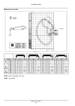
Page 41: ...1 3 5 2 4 4 3 2 9 4 7 3 9 Z2 3 5 2 3 3 7 2 5 3 7 2 5 3 7 2 5 Z1 3 0 2 1 1 6 3 5 2 4 1 8 4 3 2 9 2 2 4 8 3 8 2 2 LD 2 45 m Z3 3 0 2 1 3 4 2 4 3 4 2 9 3 4 3 8 Z2 3 6 2 3 1 6 3 6 2 6 1 9 3 6 3 0 2 2 3 6...

Page 42: ...vice pressure 360 10 bar 5220 0 145 0 psi Engine speed 1800 RPM Auxiliary pump volume 8 6 cm 0 52 in Main pump volume 40 cm 2 44 in Maximum flow rate at 1750 RPM heavy 70 l min 18 5 US gpm Gear pump M...

Page 43: ...4 in rev Total reduction ratio 20 7 Maximum oil delivery 74 l min 19 5 US gpm Hydraulic motor maximum pressure 320 bar 4640 0 psi Maximum input speed 1321 RPM Gearbox output torque 5904 N m 4354 6 lb...

Page 44: ...M 35 km h 21 7 mph 1514 RPM N max at Vgmin 20 km h 12 43 mph 2200 RPM 35 km h 21 75 mph 4150 RPM Nmax 4500 RPM Rated pressure PN 20 km h 12 43 mph 400 bar 5800 0 psi 35 km h 21 75 mph 400 bar 5800 0 p...

Page 45: ...ge 24 V Batteries 2 x 12 V Batteries rating 100 A h Alternator 70 A Starter motor 4 kW 5 44 Hp Buckets Width Weight Heaped capacity SAE capacity Number of teeth 600 mm 23 6 in 330 kg 727 5 lb 0 28 m 9...

Page 46: ...gement in line Valves per cylinders 2 Bore 104 mm 4 09 in Stroke 132 mm 5 20 in Power 90 kW 122 4 Hp at 2000 RPM Maximum torque 525 N m 387 2 lb ft at 1200 RPM Rated rpm 2000 RPM 50 Injection pump 24V...

Page 47: ...draulic Fluid 68 HV MS 1216 DIN 51524 HVLP68 ISO VG 68 Air conditioning 820 g 50 28 9 oz 1 8 R134a Windscreen washer 1 5 l 0 4 US gal TUTELA PROFESSIONAL SC35 Grease Ball bearing 13 5 kg 29 8 lb Moly...

Page 48: ...chine identification plate B Engine identification plate 1 Model and category Hydraulic Excavator 6 Engine type 2 Machine serial number 7 Engine emission stage approval number 3 Nominal Power 8 Engine...

Page 49: ...death or se rious injury W0143A Any damage fire corrosion or modification will weaken the structure and reduce your protection If this occurs the Protective Structure MUST be replaced Contact your dea...

Page 50: ...SERVICE MANUAL Engine WX TIER 3 47500167A 31 01 2013 10...

Page 51: ...This as a preview PDF file from best manuals com Download full PDF manual at best manuals com...

Reviews: