background image

Safety, general information and standard torque data

Safety

This symbol means ATTENTION! BECOME ALERT! YOUR SAFETY IS INVOLVED.
The message that follows the symbol contains important information about safety.
Carefully read the message.
Make sure you fully understand the causes of possible injury or death.

To prevent injury always follow the Warning, Caution and Danger notes in this section and throughout the manual.
Put the warning tag shown below on the key for the key switch when servicing or repairing the machine.
One warning tag is supplied with each machine.
Additional tags are available from your service parts supplier.

WARNING

Read the operator's manual to familiarize yourself with the correct control functions.

WARNING

Operate the machine and equipment controls from the seat position only.
Any other method could result in serious injury.

WARNING

This is a one man machine, no riders allowed.

WARNING

Before starting engine, study Operator’s Manual safety messages.
Read all safety signs on machine.
Clear the area of other persons.
Learn and practice safe use of controls before operating.
It is your responsibility to understand and follow manufacturers instructions on machine operation, ser-
vice and to observe pertinent laws and regulations.
Operator's and Service Manuals may be obtained from your CASE dealer.

WARNING

If you wear clothing that is too loose or do not use the correct safety equipment for your job, you can
be injured.
Always wear clothing that will not catch on objects.
Extra safety equipment that can be required includes hard hat, safety shoes, ear protection, eye or face
protection, heavy gloves and reflector clothing.

WARNING

When working in the area of the fan belt with the engine running, avoid loose clothing if possible, and
use extreme caution.

WARNING

When doing checks and tests on the equipment hydraulics, follow the procedures as they are written.
DO NOT change the procedure.

WARNING

When putting the hydraulic cylinders on this machine through the necessary cycles to check operation
or to remove air from a circuit, make sure all people are out of the way.

WARNING

Use insulated gloves or mittens when working with hot parts.

84402832 NA - May 2011

1001-4

Summary of Contents for CX250C

Page 1: ...ght 2011 CNH America LLC All Rights Reserved Case is a registered trademark of CNH America LLC Racine Wisconsin 53404 U S A Part number 84402832 1st edition English August 2011 SERVICE MANUAL CX350C T...

Page 2: ...Section 1001 Safety general information and standard torque data 84402832 NA May 2011...

Page 3: ...84402832 NA May 2011...

Page 4: ...CONTENTS GENERAL INFORMATION 3 Safety 4 ROPS Judgment Method 6 Standard Torque Data For Cap Screws And Nuts 10 84402832 NA May 2011 1001 1 Copyright 2011 CNH FRANCE S A PRINTED IN FRANCE...

Page 5: ...ore information Please click here Then get the complete manual NOTE If there is no response to click on the link above please download the PDF document first and then click on it Have any questions pl...

Page 6: ...84402832 NA May 2011 1001 2 Copyright 2011 CNH FRANCE S A PRINTED IN FRANCE...

Page 7: ...ry DO NOT DRY BEARINGS WITH COMPRESSED AIR NEEDLE BEARINGS Before you press needle bearings in a bore always remove any metal protrusions in the bore or edge of the bore Before you press bearings into...

Page 8: ...on machine Clear the area of other persons Learn and practice safe use of controls before operating It is your responsibility to understand and follow manufacturers instructions on machine operation...

Page 9: ...ly encloses the eyes approved goggles or other approved eye protectors WARNING Use suitable floor service jacks or chain hoist to raise wheels or tracks off the floor Always block machine in place wit...

Page 10: ...r each class If the weight is exceeded there is a danger that the cab could be damaged and the operator could die or sustain a serious injury when the machine falls over If the weight exceeds the stip...

Page 11: ...etermined in the same way for all machines a Ground point With the tip of the bucket in contact with the ground surface at maximum work radius if the position in the diagram that overlaps with the cab...

Page 12: ...of the anchoring part at the left rear of the cab Modifications that effect the strength of the ROPS of a cab A forbidden all modifications red part All modifications grinding welding drilling holes...

Page 13: ...n and standard torque data B series Cab In general high cabs do not satisfy the ROPS criteria It is necessary to consult with our company to check if the high cab model satisfies the ROPS criteria 844...

Page 14: ...cking to the bolt when it is removed clean the old Loctite off with cleaning fluid dry the bolt then apply 2 3 drops of Loctite to the thread section of the bolt Torque table Bolt nominal diameter siz...

Page 15: ...Section 1002A Specifications 84402832 NA May 2011...

Page 16: ...84402832 NA May 2011...

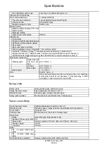
Page 17: ...Side Work System 4 Operating Device 4 Swing Units 5 Travel Lower Body 5 Hydraulic Equipment 6 Hydraulic Device 6 Control Valve and Cylinder 6 Capacities Filters 6 Coolant and Oil Capacities 6 Hydrauli...

Page 18: ...84402832 NA May 2011 1002A 2 Copyright 2011 CNH FRANCE S A PRINTED IN FRANCE...

Page 19: ...Unit Dimensions Main unit length 6010 mm Main unit width 3200 mm 600 G shoe Upper swing body width 3030 mm Cab width 1000 mm Main unit height 3160 mm Swing radius rear end 3550 mm Swing body rear end...

Page 20: ...short 2 21 m Arm length 3250 mm 4040 mm 2630 mm 2210 mm Bucket radius 1680 mm Bucket wrist angle 173 Maximum digging radius 11170 mm 11900 mm 10670 mm 10200 mm Maximum digging radius at ground line 10...

Page 21: ...0 W x 2 Boom side 24 V 70 W x 1 Interior light 4 V 10 W x 1 Horn Electric horn x 2 Other Wiper with intermittent function window washer air conditioner 4 rear view mirrors 2 on cab sides 1 front right...

Page 22: ...spool x 1 Operating method Hydraulic pilot type travel swing and operating machine Cylinder No of cylinders x tube bore rod diameter stroke Boom cylinder 2 x D145 mm D100 mm 1495 mm Arm cylinder 1 x D...

Page 23: ...Section 1002B Main Equipment Table 84402832 NA May 2011...

Reviews: