CHAPTER 3 - INSTRUMENTS AND CONTROLS
3-12
Issued 8-04 Bur
6-34551NA
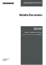
HEATING, VENTILATION AND AIR-CONDITIONING CONTROL
CT02D158
Figure 23
1. ON/OFF
This push button (1) is for turning the system on
or off.
When the system is turned on it will operate at
the same setting as selected for previous use.
2. AIR-CONDITIONING SWITCH
This switch (2) turns the air-conditioning on/off.
When it is on, the indicator lamp on the switch
comes on.
3. VENTILATION
These push buttons (3) allows the air flow to be
increased or reduced. To increase the flow of air,
press the top button. To decrease the flow of air,
press the lower button. The segments increase
or reduce depending on the flow selected.
4. TEMPERATURE
These push buttons (4) help increase or reduce
the temperature. To increase the temperature,
press the Right-Hand button. To decrease the
temperature, press the Left-Hand button. The
temperature is controlled by the increase or
reduction in the number of segments.
5. AIR FLOW DIRECTION
These push buttons (5) are used for the selection
of three types of air flow direction:
Via the top front air vent.
Via the top front and rear air vents.
Via the top and lower rear air vents.
To select the type of air flow, press the button (5)
relating to the type of air flow desired. Depending
on the selected type, a built-in indicator lamp
comes on.
6. WINDSHIELD DEFROSTER
This button (6) allows the windshield to be
d e f r o s t e d . P r e s s t h e b u t t o n , w i n d s h i e l d
defrosting is carried out and a built-in indicator
lamp comes on. To stop, press the button again,
the indicator lamp goes off.
7. AIR RECYCLING
This button (7) allows two different types of air
circulation to be selected:
External air circulation.
Internal air circulation.
Each time the button is pressed, the type of
circulation will be changed. Depending on the
selected type, a built-in indicator lamp comes on.
1
3
4
5
2
7
6
Summary of Contents for CX135SR
Page 6: ...IV Issued 8 04 Bur 6 34551NA CHAPTER 9 INDEX...
Page 12: ...CHAPTER 1 GENERAL INFORMATION 1 6 Issued 8 04 Bur 6 34551NA NOTES...
Page 14: ...CHAPTER 2 SAFETY DECALS AND HAND SIGNALS 2 2 Issued 8 04 Bur 6 34551NA NOTES...
Page 60: ...CHAPTER 3 INSTRUMENTS AND CONTROLS 3 32 Issued 8 04 Bur 6 34551NA...
Page 62: ...CHAPTER 4 OPERATING INSTRUCTIONS 4 2 Issued 8 04 Bur 6 34551NA...
Page 82: ...CHAPTER 4 OPERATING INSTRUCTIONS 4 22 Issued 8 04 Bur 6 34551NA NOTES...
Page 132: ...CHAPTER 5 LUBRICATION FILTERS AND FLUIDS 5 50 Issued 8 04 Bur 6 34551NA NOTES...
Page 134: ...CHAPTER 6 MAINTENANCE AND ADJUSTMENTS 6 2 Issued 8 04 Bur 6 34551NA...
Page 152: ...CHAPTER 6 MAINTENANCE AND ADJUSTMENTS 6 20 Issued 8 04 Bur 6 34551NA NOTES...
Page 154: ...CHAPTER 7 ELECTRICAL 7 2 Issued 8 04 Bur 6 34551NA NOTES...
Page 164: ...CHAPTER 8 SPECIFICATIONS 8 2 Issued 8 04 Bur 6 34551NA...
Page 183: ...CHAPTER 8 SPECIFICATIONS 8 21 6 34551NA Issued 8 04 Bur NOTES...
Page 184: ...CHAPTER 8 SPECIFICATIONS 8 22 Issued 8 04 Bur 6 34551NA...