


3 – ANhyDRoUS CoNfIGURATIoN – continued
3 – ANhyDRoUS CoNfIGURATIoN – continued
3.4 Nh
3
Drive Set-up
a) Select NH3 Drive [Yes]
b) Press ‘Setup’
c) Assign NH3 Drive Serial
Numbers (starting w/
modules on LH side)
d) Select Drive Type [Servo
or PWM]
e) Select Master Valve Type
f) Select Pump Disarm
fg) Select Sec Off Behavior
[Lock at Last or Turn Off]
h) Enter Drive Meter Cal
Number
(Pulses/Gal)
Note:
Pulses/gallon will be found on the liquid flow meter. Some
flow meters are measure in pulses/10 gallons. If this is the case,
divide that value by 10 to find pulses/gallon.
i) Press ‘Done’
3.5 Master Switch Box
(If Equipped with External Switch Box)
a) Select Master Sw Box [Yes]
b) Press ‘Setup’
c) Verify Serial Number of
Switch Box
d) Select Footswitch (if
installed)
e) Press “Done’
3.6 Implement Switch
(If equipped with Toolbar Mounted Implement Switch)
a) Select Imp Switch [Yes]
b) Press ‘Setup’
c) Select Imp Switch
Serial Number
d) Select Switch Polarity
Note:
Determine by raising and lowering the implement and
watch the Implement Status Arrow in Status/Warning Area for
proper operation.
e) Press ‘Done’
Note:
#1 EHR work switch on Magnum & Steiger tractors can be
used as an implement switch (the #1 EHR must be cycled once
after each start up to display the status arrow).
3.7 Section Switch Box (If equipped with
External Section Switch Box or Desire
Manual valve Section Control through Run Screens)
a) Select Section Switch Box
[Yes]
b) Press ‘Setup’
c) Select Config Mode [Auto]
or [Manual] for custom
d) Verify Sw Box Serial
Number (if equipped w/
external switchbox)
Note:
If no external switchbox
is installed, User Defined
Windows
can be assigned
to a Run Screen
(
Toolbox>layout
)
4 – WoRk CoNDITIoN – REQUIRED foR oPERATIoN
4 – WoRk CoNDITIoN – REQUIRED foR oPERATIoN
(continued)
Work Condition>layer
IMPoRTANT!
The settings below are linked to a
work condition. These must be selected or checked
whenever a work condition is created/changed: product type,
application rate, drive settings, product delay, product layer
control and product control.
NoTE!
A work condition name could be for a crop type, field
condition, or weather condition, etc.
NoTE!
This setup is required for logging/ mapping data and
using Overlap & Boundary Control.
4.1 Preparation
a) Insert a data card in the display
b) Create/select a Grower/Farm/Field/Task and Crop Type
(
Performance > Profile
)
4.2 Product Setup - continued
NoTE!
App Rate will not
be able to be adjusted
outside of this range
NoTE!
App Rates are
measured in pounds of
actual Nitrogen, NOT
pounds of NH
3
.
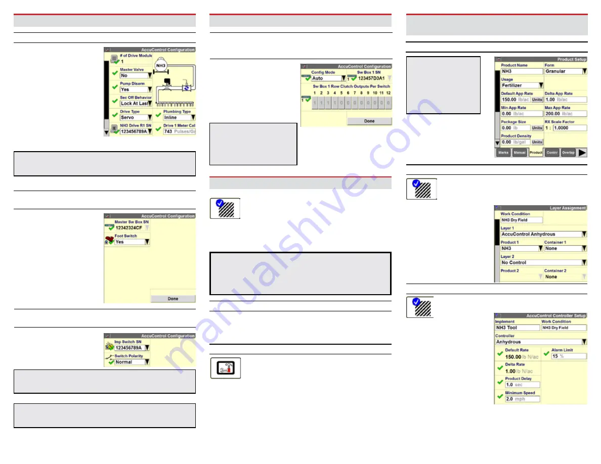
4.2 Product Setup
Toolbox> Product
a) Name the product (ex. NH3)
b) Select form type for product [Granular]
c) Select Usage [Fertilizer]
d) Enter Default Application Rate
e) Enter Minimum Application Rate & Maximum
Application Rate
4.3 Product layer Assignment
Work Condition> layer
Assign a product to a control section
of the Applicator.
a) Select/Create a
Work Condition
b) Select Layer 1 Control
Type [AccuControl
Anhydrous]
c) Select Product for
Layer 1 Control
d) Assign Additional Layers
as needed
4.4 Controller Setup – Anhydrous (if equipped)
Work Condition>Control
a) Verify Implement
b) Verify Work Condition
c) Select Controller
[Anhydrous]
d) Product Delay – Default
1.0 sec. (see section 7
for Product Delay
Measurement procedure)
e) Enter the Minimum
Speed (if ground speed
drops below this speed,
applicator will apply at
this set speed)
f) Enter value for Off-target
Alarm Limit