


FW500 Service Manual
26 8/31/2015
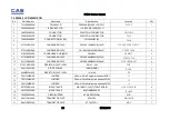
7.
Error Messages & Solution
Error Message
on Display
Description
Solution
"Err 0"
The "Err 0" occurs when scale is not stable.
Remove unstable facts.
"Err 1"
The "Err 1" occurs when a current zero point has
shifted from the last span calibration.
Please call your CAS
dealer.
"Err 2"
The "Err 2" is not a real error. Only it prompts
return CAL switch to the normal position.
Please call your CAS
dealer.
"Err 3"
The "Err 3" is an overload error.
Please remove the
weight.
"Err 9"
The "Err 9" is no weight error. When scale is in
counting mode, you must load the weight.
If you have no weight on your scale, you can see
this error message.
Please load the weight
on your tray.
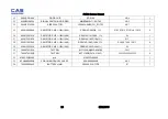
“Err 11”
The "Err 11" means a writing error of the internal
nonvolatile memory. To recognize this error, be
sure to check the voltage on the circuit and do
calibration procedures.
If it still has "Err 11",
replace the digital
module.
“Err 12”
The "Err 12" warns that the scale has lost the
parameters for weighing regulations or has lost
the factors for a digital span calculation.
Enter each condition
codes again.
Please try a span
calibration again if still
not fixed.
“Err 14”
The "Err 14" means calibration range is not
correct.
Please call your CAS
dealer.
Summary of Contents for FW500
Page 1: ...FW500 Service Manual 1 8 31 2015 FW500 SE SERVICE MANUAL Revision 0 2013 02 19 ...
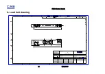
Page 6: ...FW500 Service Manual 6 8 31 2015 1 4 Dimension ...
Page 7: ...FW500 Service Manual 7 8 31 2015 1 5 Dimension TILTING DISPLAY TYPE ...
Page 8: ...FW500 Service Manual 8 8 31 2015 1 6 Sealing method ...
Page 15: ...FW500 Service Manual 15 8 31 2015 3 2 Circuit Diagram 3 2 1 FW500C Main PCB ...
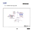
Page 16: ...FW500 Service Manual 16 8 31 2015 3 2 2 FW500C Rear Display PCB ...
Page 17: ...FW500 Service Manual 17 8 31 2015 3 2 3 FW500E Main PCB ...
Page 18: ...FW500 Service Manual 18 8 31 2015 ...
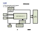
Page 19: ...FW500 Service Manual 19 8 31 2015 3 2 4 FW500 E Rear Display PCB ...
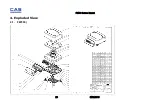
Page 20: ...FW500 Service Manual 20 8 31 2015 4 Exploded View 4 1 FW500 ...
Page 22: ...FW500 Service Manual 22 8 31 2015 6 Part Location 6 1 FW500C Main PCB Top Bottom ...
Page 23: ...FW500 Service Manual 23 8 31 2015 6 2 FW500E Main PCB Top Bottom ...
Page 24: ...FW500 Service Manual 24 8 31 2015 6 3 FW500C Rear Display PCB Top Bottom ...
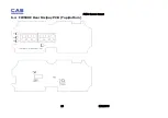
Page 25: ...FW500 Service Manual 25 8 31 2015 6 4 FW500E Rear Dislpay PCB Top Bottom ...


