


EB
Service Manual
29 2007/06/13
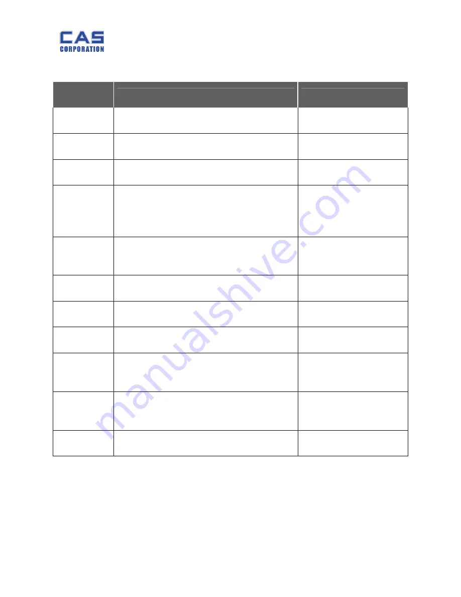
7. Error Messages & Solution
Error Message
on Display
Description
Solution
"Err 1"
The "Err 1" occurs when a current zero point has
shifted from the last span calibration.
Please call your CAS
dealer.
"Err 2"
The "Err 2" is not a real error. Only it prompts return
CAL switch to the normal position.
Please call your CAS
dealer.
"Err 10"
The "Err 10" means a failure of the analog module.
Replace the analog module by a new one.
Please call your CAS
dealer.
"Err 11"
The "Err 11" means a writing error of the internal
nonvolatile memory. To recognize this error, be sure
to check the voltage on the circuit and do calibration
procedures.
Please call your CAS
dealer.
"Err 12"
The "Err 12" warns that the scale has lost the
parameters for weighing regulations or has lost the
factors for a digital span calculation.
Please call your CAS
dealer.
"Err 13"
The "Err 13" means the soft key code is broken.
Please call your CAS
dealer.
“Help 1”
“Help 1” is marked in case of zero extent exceeded.
Please remove the item
from the platter.
“Help 3”
“Help 3” is marked in case sale number of times
exceeds 999 or add totalprice is over 9999.99
Spend again accumulated
TTP value after delete
“Help 4”
- “Help 4” is marked in case Euro factor value is “0”
at Euro rate application.
- Input again Euro factor
value.
Err 4”
- “Help 4”
Is marked when input smaller Pay cost
than Total sale amount of money at Pay function
use.
- Pay value than Total sale
amount of money bigger
value or same value input
“Help 5”
“Help 5” is marked when DTP number of times is
more than 50000 times.
Spend again accumulated
DTP value after delete
Summary of Contents for EB Series
Page 1: ...EB Service Manual 1 2007 06 13 EB SERVICE MANUAL ...
Page 6: ...EB Service Manual 6 2007 06 13 1 4 Dimension ...
Page 9: ...EB Service Manual 9 2007 06 13 1 6 Sealing Method PLATE ...
Page 10: ...EB Service Manual 10 2007 06 13 STICKER ...
Page 22: ...EB Service Manual 22 2007 06 13 4 Exploded View ...
Page 23: ...EB Service Manual 23 2007 06 13 5 Load Cell drawing ...
Page 24: ...EB Service Manual 24 2007 06 13 6 Part Location 6 1 Main PCB Top ...
Page 25: ...EB Service Manual 25 2007 06 13 6 2 Main PCB Bottom ...
Page 26: ...EB Service Manual 26 2007 06 13 6 3 Rear Display PCB Top 6 4 Rear Display PCB Bottom ...
Page 27: ...EB Service Manual 27 2007 06 13 6 5 Terminal PCB Top 6 6 Terminal PCB Bottom ...
Page 28: ...EB Service Manual 28 2007 06 13 6 7 Cal PCB Top ...


