Cartechno NA-VL2DVD900 Installation Instructions Manual Download Page 18


Version 02.10.2015


NA-VL2DVD900


Pa

ge

18


5.


Frequently asked questions 
 

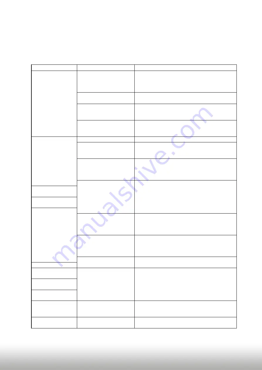
For any troubles which may occur, check the following table for a solu

ti

on before reques

ti

ng 

support from your vendor. 


Symptom 

Reason 

Possible solution 

No picture/black 

picture (factory 

picture). 

Not all connectors have been 

reconnected to factory head-

unit or monitor 

aft

er 

installa

ti

on. 

Connect missing connectors. 

No power on CAN-bus box (all 

LED CAN-bus box are o

). 

Check power supply of CAN-bus box. Check CAN-bus 

connec

ti

on of CAN-bus box. 

CAN-bus box connected to 

CAN-bus in wrong place. 

Refer to the manual where to connected to the CAN-

bus. If not men

ti

oned, try another place to connect to 

the CAN-bus. 

No power on video-interface 

(all LED video-interface are 

o

). 

Check whether CAN-bus box de12V ACC on red 

wire output of 8pin to 6pin cable. If not cut wire and 

supply ACC +12V directly to video-interface. 

No picture/black 

picture/white picture 

(inserted picture) but 

factory picture is OK. 

No picture from video source.  Check on other monitor whether video source is OK. 
No video-source connected to 

the selected interface input. 

Check s

etti

ngs dips 1 to 3 of video interface which 

inputs are 

acti

vated and switch to corresponding 

input(s). 

LVDS cables plugged in wrong 

place. 

Double-check whether order of LVDS cables is exactly 

connected according to manual. Plugging into head-

unit does not work when the manual says to plug into 

monitor and vice versa. 

Wrong monitor s

etti

ngs of 

video-interface. 

Try di

erent combina

ti

ons of dips 7 and 8 of video-

interface. Unplug 6pin power a

ft

er each change. 

Inserted picture totally 

wrong size or posi

ti

on. 

Inserted picture double 

or 4 

ti

mes on monitor. 

Inserted picture 

distorted, 

ickering or 

running ver

ti

cally. 

Video sources output set to 

AUTO or MULTI which causes 

a con

ict with the interfaces 

auto detec

ti

on. 

Set video source output 

xed to PAL or NTSC. It is best 

to set all video sources to the same standard. 

If error occurs only 

aft

er 

source switching: Connected 

sources are not set to the 

same TV standard. 

Set all video sources to the same standard. 

Some interfaces can only 

handle NTSC input. 

Check manual whether there is a limita

ti

on to NTSC 

men

ti

oned. If yes, set source 

xed to NTSC output. 

Inserted picture b/w. 

Inserted picture qual. 

bad. 

Picture s

etti

ngs have not been 

adjusted. 

Use the 3 b

utt

ons and the interface's OSD to adjust the 

picture s

etti

ngs for the corresponding video input. 

Inserted picture size 

slightly wrong. 

Inserted picture 

posi

ti

on wrong. 

Camera input picture 

ickers. 

Camera is being tested under 

uorescent light which shines 

directly into the camera. 

Test camera under natural light outside the garage. 

Camera input picture is 

bluish. 

Protec

ti

on s

ti

cker not 

removed from camera lens. 

Remove protec

ti

on s

ti

cker. 


Summary of Contents for NA-VL2DVD900

Page 1: ...switching to rear view camera input on engagement of reverse gear RGB input for after market navigation Video in motion ONLY for connected video sources Compatible with factory rear view camera AV in...

Page 2: ...stallation 2 1 Place of installation 2 2 Connection schema 2 3 Connecting video interface and GM LAN box 2 4 Connection to the factory monitor 2 5 Connecting peripheral devices 2 5 1 After market RGB...

Page 3: ...or DVD upgrades Changes updates of the vehicle s software can cause malfunctions of the interface We o er free software updates for our interfaces for one year after purchase To receive a free update...

Page 4: ...possibly existing factory audio AUX input or a FM modulator Factory rear view camera Automatic switch back from inserted video to factory rear view camera only while reverse gear is engaged To delay...

Page 5: ...ommended to enable only the required inputs for the disabled will be skipped when switching through the video interfaces inputs 1 4 2 RGB video input signal selection for after market navigation Dip 4...

Page 6: ...the interface to see which combination gives the best picture quality and size some may give no picture It is possible to rst hot plug through the dip combinations but if you do not experience any cha...

Page 7: ...Version 02 10 2015 NA VL2DVD900 Page 7 2 2 Connectionschema...

Page 8: ...le to the male 4pin Micro Fit connector of the GM LAN box Note Check LEDs on CAN box after reconnecting the battery one must be on 1 GM LAN 2 12V Battery 3 Ground Note GM LAN position can be di erent...

Page 9: ...ble Connect female GVIF connector of the GVIF cable to the male GVIF connector of the factory monitor 2 5 Connecting peripheral devices It is possible to connect 2 after market AV sources an after mar...

Page 10: ...rket RGB navigation Connect female 8pin connector of the RGB cable to the male 8pin connector of the video interface The loose grey wires have no function and have to be isolated Connect male 6pin con...

Page 11: ...ct female 6pin connector of the video cable to male 6pin connector of the video interface Connect video RCA of the AV source 1 to the female RCA connector Video IN 1 of the video cable Connect video R...

Page 12: ...io pins Definition Audio input signal R L of source AV2 Audio input signal R L of source AV1 5 6 Audio output signal R L of factory audio AUX or FM modulator 7 Ground Note If only one AV source shall...

Page 13: ...8pin cable should carry 12V while the reverse gear is engaged Note Do not forget to set dip5 of video interface to ON before testing 2 5 4 1 Case 1 GM LAN box detects reverse gear If the CAN bus inte...

Page 14: ...ctronic interference a normally open relay e g AC RW 1230 with wiring AC RS5 or lter e g AC PNF RVC is required Below schema shows the use of a relay normally open Cut the green cable of the 6pin to 8...

Page 15: ...he after market rear view camera to the female RCA port of the video interface which is labeled as CAM Note Picture settings for CAM input must be done in AV2 2 6 Connecting video interface and keypad...

Page 16: ...one separately for RGB AV1 and AV2 while the corresponding input is selected and visible on the monitor AV2 and CAM share the same settings which must be adjusted in AV2 Note The OSD menu is only show...

Page 17: ...is connected when switching from video IN1 to video IN2 also the sound will be switched Note The white wire of the 6pin cable can be used with a 5 12V pulse to switch the video sources alternatively 3...

Page 18: ...der of LVDS cables is exactly connected according to manual Plugging into head unit does not work when the manual says to plug into monitor and vice versa Wrong monitor settings of video interface Try...

Page 19: ...ite wire of 6pin to 8pin cable and apply 12V impulses for AV switching Pressed too short For video source switching a longer press of about 2 5 seconds is required Not possible to switch video sources...

Reviews: