background image


TB0355A 

Page 5 of 8 

09/27/05 

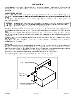
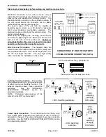
CONNECTIONS AT REAR OF UNIT WITH 


CP4688-10 POWER CONNECTOR (10-Pin) 

(2) #18 AWG BRN  

(#16 -  2  SPKR)  

2 - SPKR - C onnect for  

same phase (+ to +)  

SP

K

R


SP

K

R


PO

S


PO

S


RA

D


RA

D


AU

X


CU

T


NE

G


NE

G


• • • • • • • • • • 

#22 AWG WHT  (See below)  

#22 AWG GRN ( See bel ow)  

(2) #22 AWG  BLU  
Connect to output 

jac k, ter mi nals  or  

speaker of r adi o 

#14 AWG R ED  

Use  s ec ond  l ead 

for 2 - SPKR  

#14 AWG BLK 

Use  s ec ond  l ead 

for 2 - SPKR  

RADIO  

BAT 

+VDC Switching examples 

HORN 

RING  

SWITCH 

+VDC 

AUX 

SPLIC E 

HORN 

RING  

SWITCH 

+VDC 

AUX 

Added 

SPDT  

Switc h 

HORN 

HORN 


-VDC 

switching 

example 

Must cut AUX P  

option resistors 

MOMENTARY 

FOOT 

SWITCH 

AUX 


-VDC 

switching 

example 

Must cut CUT P  

option resistors 

ADDED 

DOOR 

SWITCH 

CUT 

+VDC Switching 

example 

DOOR 

SWITCH 

+VDC 

CUT 

SPLIC E 

DOME 
LIGHT 

ELECTRICAL CONNECTIONS 


Disconnect vehicle battery before making any electrical connections. 


Electrical connections to the unit are made using a 
removable terminal block plug located on the back.  A 
label on the unit identifies the terminal function.  You 
should install the connector on the unit before wiring.  If 
the unit needs service the connector can be easily 
removed without unwiring the connector. 
The power supply of the unit must be capable of 
delivering peak currents up to 50 amps for adequate 
short circuit protection and reliable operation.  The 
preferred source is directly at the vehicle battery.  The 
unit is internally fused. 
Attach leads by stripping 3/8", inserting into connector 
and clamp by tightening screw.  Make sure the screw is 
tight and the wire can't be pulled out.  

Failure to 

adequately tighten the screw can result in improper 
operation or burning the connector and wire


Wire Size and Termination

 - The diagram shows the 

minimum wire size used for each connection, along with 
recommended lead color.  If the wire is longer than 10 ft. 
use the next larger wire size.  Use only high quality 
crimp connectors for installation on the vehicle. 


Auxiliary Input Connection

 - The Auxiliary 

Input allows activation by an external source 
of either the Horn or Man/Phsr function.  The 
adjacent diagram shows three connection 
examples.  See the INSTALLER-
SELECTABLE OPTIONS section for 
programming details. 
NOTE:  Permanent disconnection of the 
vehicle horn is NOT recommended. 


Cutout Input Connection

 - The Cutout Input turns off any siren 

tone output when activated, and remains off until a control is 
activated or changed.  The adjacent diagram shows two connection 
examples.  See the INSTALLER-SELECTABLE OPTIONS section 
for programming details. 
 

10-P Terminal Block Plug  (CP4688-10)

Header 

Install with screw terminals face down

Summary of Contents for SA-500-16 14V

Page 1: ...F F O N SA 500 RAD INSTALLATION AND OPERATING MANUAL SA 500 16 14V SPECIAL PROGRAMMED WITH YELP OVERRIDE ON THE MAN PHSR BUTTON Carson is a trademark of Carson Manufacturing Company Inc Sound Hazard Sound level from siren speaker 120dBA 10 feet may cause hearing damage Do not operate siren without adequate hearing protection for you and anyone in immediate vicinity Ref OSHA 1910 95 for occupationa...

Page 2: ...EIGHT 5 pounds NIGHT VISIBILITY Backlit front control panel when power is on PROTECTION High Voltage Siren output stops with input voltage above highest rating Stops high output power from blowing speaker Reverse Polarity Fuse s blows when power is wired backwards Shorted Output Fuse s blows if speaker shorts a common problem NOTICE Due to continuous product improvements we must reserve the right ...

Page 3: ...l damage mounting bolts must not enter case more than 1 4 Wiring Use wiring capable of handling the current required Make sure all connections are tight Route wiring to prevent wear overheating and interference with air bag deployment Install and check all wiring before connection to vehicle battery Testing Test all siren functions after installation to assure proper operation Test vehicle operati...

Page 4: ...The auxiliary input is normally activated by connecting to positive To activate by connecting to ground cut the two jumper resistors labeled AUX P Cutout Input Polarity The cutout input is normally activated by connecting to positive To activate by connecting to ground cut the two jumper resistors labeled CUT P Two Tone Two Tone can replace Phaser by cutting the jumper resistor labeled T T Phaser ...

Page 5: ...e of delivering peak currents up to 50 amps for adequate short circuit protection and reliable operation The preferred source is directly at the vehicle battery The unit is internally fused Attach leads by stripping 3 8 inserting into connector and clamp by tightening screw Make sure the screw is tight and the wire can t be pulled out Failure to adequately tighten the screw can result in improper ...

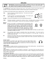
Page 6: ...ptional operation includes replacement of the Phaser tone with Two Tone or disabling the Phaser tone entirely Horn This push button switch provides a simulated air horn tone while pressed This can be used to supplement the normal vehicle horn and is useful at intersections or in low noise areas This tone will override all other siren tones PA Pressing the microphone button in any mode except Radio...

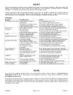
Page 7: ...erly The input voltage must be greater than lowest rating Intermittent siren tone High Voltage Protection Connector or connections loose Loose connection at power source Mic button activation Circuit breaker in supply connection Is the vehicle voltage regulator working properly Is the connector tight on the back of the unit Check for loose leads back to power source Is something lying on the micro...

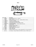
Page 8: ...l volume PA or RAD 1K ohm 5 CP4680 1 Cover with stud does not include CP4679 Chassis ATO ATC 20A Fuse 20A Automotive 6 CP4702 Knob rotary switch black substitute CP4852 black knob 7 CP4835 Label front panel CP3570 Microphone Noise Canceling CP3633 Microphone clip with mounting screws SR 15 1 Microphone strain relief 8 CP4685 Switch pushbutton Horn or Man Phsr 9 CP3962 Switch rocker power 10 CP4683...

Reviews: