
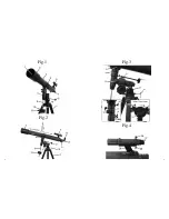

Key to Figures 1-7:
1.
Objective Lens
2.
Lens Shade
3.
Optical Tube Assembly
4.
Cradle Ring
5.
6x30mm Finder Scope
6.
Focus Knobs
7.
Equatorial Mount
8.
R.A. Flexible Cable
9.
Counter Weight Bar
10. Equatorial Mount Base
11. Tripod Legs
12. Counter Weight
13. Counter Weight Locking Screw
14. Eyepiece
15. 90° Corner Lens
16. Optical Tube Saddle Plate
17. Dec. Flexible Cable
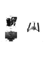
18. Latitude Turn Screws
19. Saddle Plate Lock Knob
20. Dec. Setting Circle
21. R.A. Setting Circle
22. R.A. Lock Knob
23. Latitude Dial
24. Dec. Lock Knob
25. Equatorial Mount Locking Screw
26. Finder Scope Bracket Thumb Screws
27. Finder Scope Focus Knob
28. Finder Scope Bracket
29. Finder Scope Bracket Mounting Bolts
30. Focuser Draw Tube
31. Eyepiece Holder Thumb Screw
32. 90° Corner Lens Thumb Screw
33. Cradle Ring Lock Knob
34. Accessory Tray
35. Eyepiece Holder Slots
36. Tripod Braces
37. Tripod Leg Extension Lock Knob
Assembly of your Red Planet Telescope:
Setting Up Your Tripod:
The aluminum tripod comes almost entirely preassembled and ready-to-use.
Remove the tripod from the box and pull apart the legs. Gently push down
the tripod braces (Fig. 7-36) until they are in the lowest position. You can
then extend the legs to the desired height by loosening the sliding leg exten
-
sion lock knob (Fig. 7-37), sliding the leg down the desired amount and then
tightening the extension lock knob until secure. Repeat the process with each
leg trying to keep the tripod as level as possible with the ground. You can
then attach the accessory tray (Fig. 7-34) to the tripod by lining up the thread
-
ed bottom of the accessory tray with the hole in the middle of the three tripod
braces and twisting until tight. This tray is designed with eyepiece holder
slots (Fig. 7-35) to hold spare eyepieces when not in use.
Attaching the Equatorial Mount:
Remove the equatorial mount (Fig. 1-7) from the box and twist into the posi
-
tion shown in Fig. 3. Place the bottom of the mount (Fig. 1-10) into the hole
in the top of the tripod head and secure with the mount locking screw (Fig.
3-25). Please be careful to make sure that the mount is securely attached to
the tripod.
Attaching the Counterweight:
Attach the threaded end of the counterweight bar (Fig. 1-9) into the threaded
hole in the equatorial mount (Fig. 1-7). Remove the safety screw and washer
from the end of the counterweight bar and set aside for a moment. Slide the
counterweight (Fig. 1-12) onto the bar and tighten down using the screw on
the side of the counterweight (Fig. 1-13). Be careful not to drop the coun
-
terweight. It is quite heavy and could harm you or damage your floor if
dropped. Do not worry about the position of the counterweight just yet. We
will position it properly later. Replace the safety screw and washer at the end
of the counterweight bar.
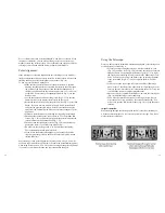
Attaching the Slow Motion Cables:
Locate the two slow motion cables (Fig. 2-8,17). Loosen the screw at the end
of each cable so that it does not protrude through the hole. Slide one cable
onto the left side of the R.A. shaft (Fig. 1-8) (located near the bottom of the
mount) and tighten down with the locking screw. Slide the remaining cable
onto the Dec. shaft (Fig. 2-17) (located near the top of the mount) and tighten
down with the locking screw. These slow motion cables will allow you to
make fine pointing adjustments to the telescope in both R.A. and declination.
This will be discussed in more detail later.
9
8
Summary of Contents for RP-400
Page 3: ...Fig 1 Fig 3 Fig 2 5 4 Fig 4...
Page 4: ...Fig 6 Fig 5 Fig 7 7 6...


