Step 3—Electric Configuration of Wireless Sensors and
Receiver
INTRODUCTION
Each Wireless Sensor contains a unique identifying code which is
sent each time it communicates with the Receiver. The Receiver
must learn this code from each sensor so that it will only respond
to its sensors and to no others. It then acts like a protecting
password, preventing Wireless Sensors in other systems from cross
communicating with this system. At each transmission, the sensor
transmits the zone number, zone temperature, and an error check-
ing code along with the identifying code. If either of the 2 codes
does not check, the temperature data is ignored. This eliminates the
possibility of erroneous temperature data being received and used.
The system learns the unique identifying codes of the sensors
during the first 10 minutes after the power is applied to the system.
If any zones are added or revised after the 10-minute learning
period, learning period may be restarted by reapplying the power.
If the system does not "learn" a zone, 2 dashes ("--") will appear
in the User Interface’s display in place of the zone temperature
indication and will result in that zone’s damper being closed.
1. Establishing Identifying Code
Use the following procedure to allow the system to install
sensor identifying codes in the Receiver. It is easiest to have
all sensors with you near the Receiver during the setup
process. When finished, sensors can be returned to their proper
locations in their zones. Remember, the following steps must
be completed within 10 minutes after power is applied.
a. Remove and reapply power to zoning system, starting
10-minute timer.
b. Press "install" button on
Receiver
once. The red LED will
come on and stay on, indicating Receiver is in setup mode.
See Fig. 1 for location of button and LED.
c. On the
sensor
, pull out battery tab to turn on
sensor
. Make
sure battery polarity is correct (+ on board m on
battery) and the contacts hold battery firmly.
d. Set the rotary switch to the applicable zone number. The
indicator is a small dot beside the screwdriver slot in the
rotary switch. See Fig. 2.
e. Press and hold install button on
sensor
for 3 sec. The
sensor’s
green LED should come on and off.
f. On the
Receiver
, the LED will flash once indicating it has
received the information. This flash may be barely notice-
able.
g. Repeat steps a. through f. for all other wireless zone
sensors
. Be sure proper zone number is set into each one.
h. On the
Receiver
, press install button once again. This will
turn off the
Receiver
red LED and exit installation mode.
2. If You Made a Mistake and Want to Start Over
You can either reinstall the identifying codes of the errant
sensor or erase the entire configuration and start over. To
reinstall the
Sensor(s)
, repeat steps 3-1-a through 3-1-h above.
To erase the entire configuration, with the red
Receiver
LED
on (if not on, momentarily press the button), press and hold the
button until the red LED goes off. The
Receiver
is now
completely cleared, it has no memory of wireless zones
previously installed. You may now start with step 3-1 above.
3. If You Want to Remove a Zone
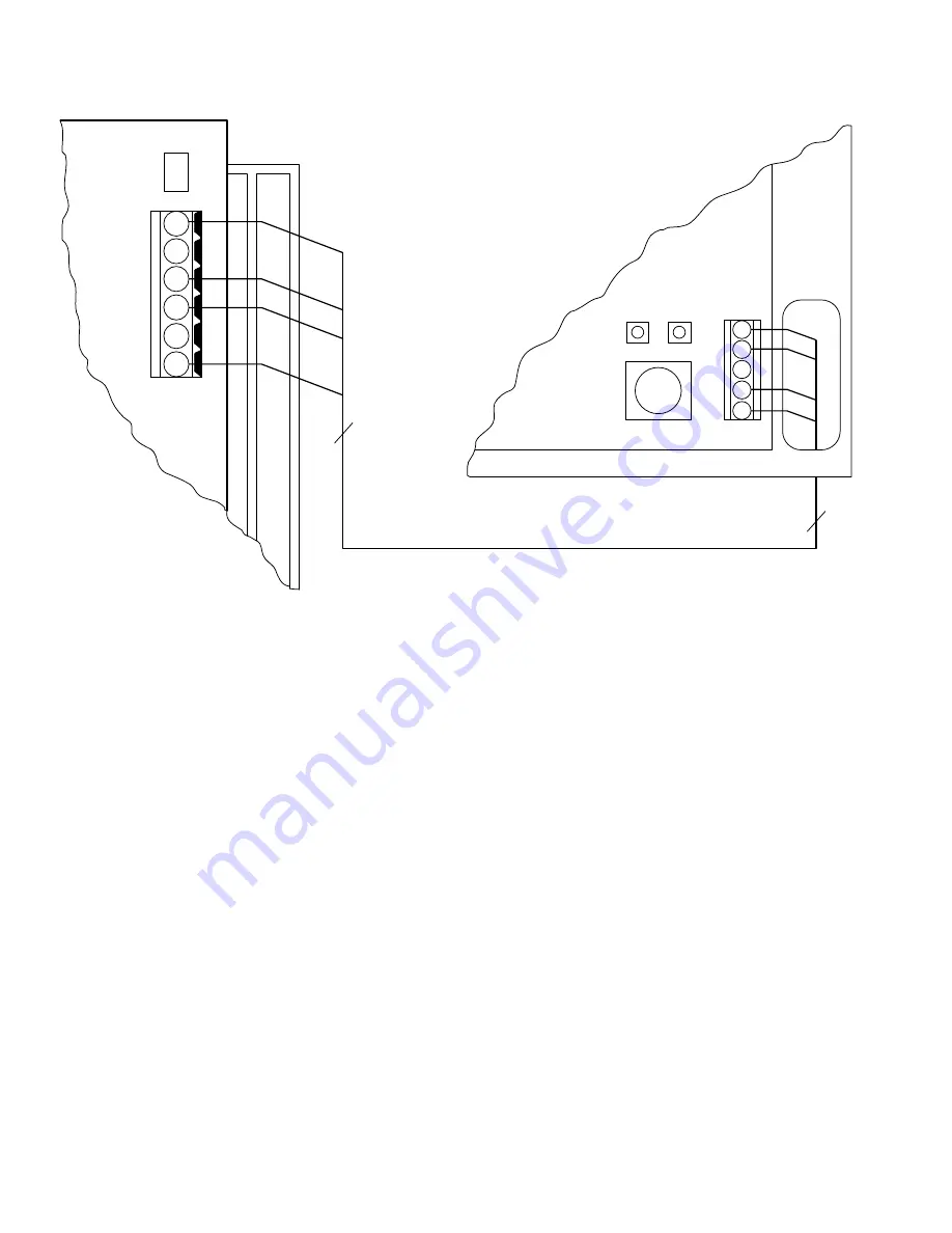
Fig. 1—Wiring of Wireless Receiver to Comfort Zone II
A98052
P
N A
D
C
N A
G
4
4
COMFORT ZONE II
EQUIPMENT CONTROLLER
WIRELESS RECEIVER
D
C
D
C
G
P
G
G
P
RED
LED
GREEN
LED
INSTALL
BUTTON
2