


57
Use Fig. 72 and Table 25 to set the DIP switches for the desired
use of the sensor.
NOTE: When an S-Bus sensor is connected to an existing net-
work, it will take 60 minutes for the network to recognize and
auto-configure itself to use the new sensor.
During the 60-minute setup period, no alarms for sensor fail-
ures (except SAT) will be issued and no economizing function
will be available.
CO
2
Sensor Wiring
When using a CO
2
sensor, the black and brown common wires
are internally connected and only one is connected to “IAQ
COM” on the W7220. Use the power from the W7220 to pow-
er the CO
2
sensor OR make sure the ground for the power sup-
plies are common. See Fig. 73 for CO
2
sensor wiring.
Fig. 73 — CO
2
Sensor Wiring
INTERFACE OVERVIEW
This section describes how to use the EconoMi$er
®
user inter-
face for:
• Keypad and menu navigation
• Settings and parameter changes
• Menu structure and selection
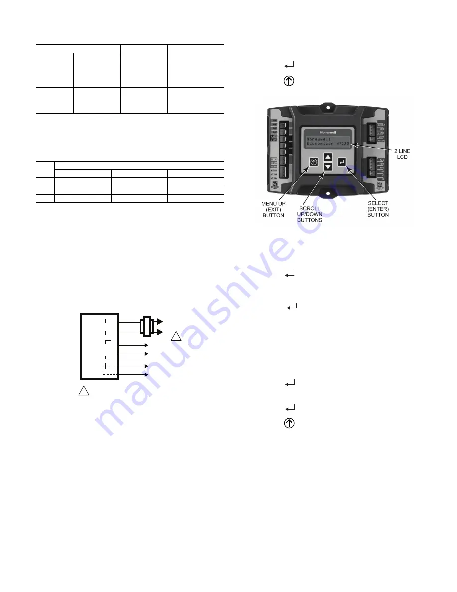
User Interface
The user interface consists of a 2-line LCD display and a 4-button
keypad on the front of the economizer controller.
Keypad
Use the four navigation buttons (see Fig. 74) to scroll through
the menus and menu items, select menu items, and to change
parameter and configuration settings.
To use the keypad when working with menus:
• Press the
▲
(Up arrow) button to move to the previous
menu.
• Press the
▼
(Down arrow) button to move to the next
menu.
• Press the
(Enter) button to display the first item in the
currently displayed menu.
• Press the
(Menu Up/Exit) button to exit a menu’s item
and return to the list of menus.
Fig. 74 — W7220 Controller Navigation Buttons
To use the keypad when working with Setpoints, System and
Advanced Settings, Checkout tests and Alarms:
1. Navigate to the desired menu.
2. Press the
(Enter) button to display the first item in the
currently displayed menu.
3. Use the
▲
and
▼
buttons to scroll to the desired
parameter.
4. Press the
(Enter) button to display the value of the
currently displayed item.
5. Press the
▲
button to increase (change) the displayed
parameter value.
6. Press the
▼
button to decrease (change) the displayed
parameter value.
NOTE: When values are displayed, pressing and holding the
▲
or
▼
button causes the display to automatically increment or
decrement.
1. Press the
(Enter) button to accept the displayed value
and store it in nonvolatile RAM. “CHANGE STORED”
displays.
2. Press the
(Enter) button to return to the current menu
parameter.
3. Press the
(Menu Up/Exit) button to return to the previ-
ous menu.
Menu Structure
Table 26 illustrates the complete hierarchy of menus and parame-
ters for the EconoMi$er
®
X system.
The Menus in display order are:
• STATUS
• SETPOINTS
• SYSTEM SETUP
• ADVANCED SETUP
• CHECKOUT
• ALARMS
NOTE: Some parameters in the menus use the letters MA or
MAT, indicating a mixed air temperature sensor location before
the cooling coil. This unit application has the control sensor
Table 24 — HH57AC081 Sensor Wiring Terminations
TERMINAL
TYPE
DESCRIPTION
NUMBER
LABEL
1
S-BUS
S-BUS
S-BUS
Communications
(Enthalpy Control
Sensor Bus)
2
S-BUS
S-BUS
S-BUS
Communications
(Enthalpy Control
Sensor Bus)
Table 25 — HH57AC081 Sensor DIP Switch
USE
DIP SWITCH POSITIONS FOR SWITCHES 1, 2, AND 3
1
2
3
DA
OFF
ON
OFF
RA
ON
OFF
OFF
OA
OFF
OFF
OFF
CO
2
SENSOR
24V
ANALOG
OUT
L1
(HOT)
L2
RED
BLACK
YELLOW
BROWN
ORANGE
GREEN
+
–
POWER SUPPLY. PROVIDE DISCONNECT
MEANS AND OVERLOAD PROTECTION
AS REQUIRED.
1
1
Summary of Contents for WeatherMaster Puron 48HC D17
Page 18: ...18 COOLING CHARGING CHARTS Fig 22 Cooling Charging Chart 15 Ton ...
Page 19: ...19 Fig 23 Cooling Charging Chart 17 5 Ton ...
Page 20: ...20 Fig 24 Cooling Charging Chart 20 Ton ...
Page 21: ...21 Fig 25 Cooling Charging Chart 25 Ton ...
Page 37: ...37 Fig 48 Unit Control Box IGC Location IGC Board IGC Board Side view Front view ...
Page 40: ...40 Fig 51 Typical IGC Wiring Diagram ...
Page 46: ...46 Fig 57 RTU Open Overlay for Economizer Wiring ...
Page 47: ...47 Fig 58 VFD Overlay for W2770 Controller Wiring ...
Page 84: ...84 Fig B 48HC D17 D28 Control Diagram 208 230 3 60 460 575 3 60 ...
Page 85: ...85 Fig C 48HC D17 D28 Power Diagram 208 230 3 60 ...
Page 86: ...86 Fig D 48HC D17 D28 Power Diagram 460 3 60 ...
Page 87: ...87 Fig E 48HC D17 D28 Power Diagram 575 3 60 ...
Page 88: ...88 Fig F 48HC D17 D28 Control Diagram with Humidi MiZer System ...
Page 89: ...89 Fig G 48HC D17 D28 Power Diagram 208 230 3 60 with Humidi MiZer System ...
Page 90: ...90 Fig H 48HC D17 D28 Power Diagram 460 3 60 with Humidi MiZer System ...
Page 91: ...91 Fig I 48HC D17 D28 Power Diagram 575 3 60 with Humidi MiZer System ...
Page 92: ...92 Fig J PremierLink System Control Wiring Diagram 50HE500891 F ...
Page 93: ...93 Fig K PremierLink System Control Wiring Diagram with Humidi MiZer System ...
Page 94: ...94 Fig L RTU OPEN Wiring Diagram ...
Page 95: ...95 Fig M RTU OPEN Wiring Diagram with Humidi MiZer System ...
Page 97: ......